|
|


 Arabic
 Bengali
 Chinese
 English
 French
 German
 Hebrew
 Hindi
Hindi Italian
 Japanese
 Korean
 Malay
Malay Polish
 Portuguese
 Spanish
 Turkish
 Ukrainian
 Vietnamese
|
ENCYCLOPEDIA OF RADIO ELECTRONICS AND ELECTRICAL ENGINEERING A simple metal detector based on the K176LE5 chip. Encyclopedia of radio electronics and electrical engineering
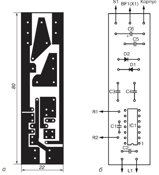
Encyclopedia of radio electronics and electrical engineering / metal detectors Among novice radio amateurs, metal detector circuits are very popular, which work on the principle of analyzing the frequency of the beat signal that occurs when two signals of similar frequency are mixed (the BFO principle). Such devices are easy to manufacture and set up, as can be seen from the following design. Schematic diagram This device is assembled on just one chip (Fig. 3.2). However, the differences lie not only in a different type of microcircuit used, but also in the circuitry of the reference and measuring oscillators. A slightly different design of the circuit made it possible to do without a variable capacitor, and also to use only one inductor. The device is based on measuring and reference oscillators, an RF oscillation detector and an indication circuit. As in the mentioned design, the device under consideration uses two simple generators made on the elements of the IC1 microcircuit. In this case, the first oscillator, which is a reference, is assembled on the elements IC1.1 and IC1.2, and the second, measuring or tunable generator is made on the elements IC1.3 and IC1.4. The operating frequency of the reference oscillator depends on the total resistance of the resistors R1 and R2, as well as on the capacitance of the capacitor C1. The trimming resistor R1 provides a coarse, and the variable resistor R2 - a smooth change in the frequency of the generator. The frequency of the measuring generator depends on the capacitance of the capacitor C2 and the inductance of the coil L1, which is the search one.
The outputs of both generators through decoupling capacitors C3 and C4 are connected to the RF oscillation detector, made on diodes D1 and D2 according to the rectified voltage doubling circuit. From the output of the detector, a low-frequency signal is fed directly to the BF1 headphones. Capacitor C5 provides load shunting at higher frequencies. When approaching the search coil L1 of the oscillatory circuit of the tunable generator to a metal object, its inductance changes, which causes a change in the operating frequency of the generator. If there is a black metal object near coil L1, its inductance increases, which leads to a decrease in the frequency of the measuring generator. The non-ferrous metal reduces the inductance of the coil L1, while the operating frequency of the generator increases. The RF signal formed as a result of mixing the signals of the measuring and reference generators after passing through the capacitors C3 and C4 is fed to the detector. In this case, the amplitude of the RF signal changes with the beat frequency. The low-frequency envelope of the RF signal is isolated by a detector made on diodes D1 and D2. Capacitor C5 provides filtering of the high-frequency component of the signal. Next, the beat signal is sent to the BF1 headphones. IC1 is powered by a 1V source B9. Details and construction All parts of a simple transistor metal detector, with the exception of the search coil L1, resistors R1 and R2, connectors X1 and X2 and switch S1, are located on a printed circuit board 80x22 mm in size, made of one-sided foil getinax or textolite. There are no special requirements for the parts used in this device. Naturally, it is recommended to use any small-sized capacitors and resistors that can be placed on a printed circuit board without any problems (Fig. 3.3).
In this device, in addition to the K176LE5 microcircuit, you can use the K176LA7, K176PU1, K176PU2, K561LA7, K564LA7 or K564LN2 microcircuits. The tuning resistor R1 can be of the SP5-2 type, and the variable resistor R2 can be of the SPO-0,5 type (other small-sized resistors are quite suitable), the capacitor C6 can be of the K50-12 type or any other for a nominal voltage of at least 10 V. The rest of the capacitors can be any small-sized ceramic, for example, type KM-6. For the manufacture of the L1 coil, it is recommended to use a piece of copper or aluminum tube with an inner diameter of 8-10 mm and a length of about 630 mm. Inside the tube, stretch a bundle of 20 pieces of PELSHO wire with a diameter of 0,5 mm, previously stretched into a PVC tube. The duralumin tube with the wires in it must be bent according to the template into a ring with a diameter of about 200 mm. The end of the wire, which is the beginning of the first turn, should be soldered to one of the terminals of the capacitor C2, the beginning of the second turn - to the end of the first turn, and so on. The end of the last turn is soldered to the second terminal of the capacitor C2. The result is a coil containing 20 turns. In the manufacture of coil L1, it is especially necessary to ensure that the ends of the shielding tube do not close, since in this case a short-circuited coil is formed. Ordinary aluminum foil can also be used to make the screen. In this case, additional rigidity of the design of the coil L1 can be given if it is placed between two disks of plywood or getinaks of appropriate sizes. As a source of sound signals, it is recommended to use any high-impedance headphones with a resistance of about 2000 ohms. The well-known TA-4 or TON-2 phone will do. The power source for V1 can be a Krona battery or two 3336L batteries connected in series. The printed circuit board with the elements located on it and the power supply are placed in any suitable plastic or wooden case. A tuning resistor R1 and a variable resistor R2, an X1 connector for connecting headphones BF1, and a switch S1 are installed on the housing cover. Search coil L1 is located at the end of any convenient handle. Establishment The adjustment of the considered metal detector should be carried out under conditions when metal objects are removed from the search coil L1 at a distance of at least one meter. First you need to adjust the operating frequencies of the reference and measuring oscillators, after setting the sliders of the resistors R1 and R2 to the middle position. It is desirable to control the frequency setting using a frequency meter or an oscilloscope. The frequency of the reference oscillator is roughly set by adjusting the resistor R1, and more precisely by the variable resistor R2. If necessary, you can choose the capacitance of the capacitor C1. Before making this adjustment, it will be necessary to disconnect the corresponding terminal of the capacitor C3 from the detector diodes and from the capacitor C4. Further, having disconnected the corresponding terminal of the capacitor C4 from the diodes of the detector and from the capacitor C3, by selecting the capacitance of the capacitor C2, you should select the frequency of the measuring generator so that its value differs from the frequency of the reference generator by about 500-1000 Hz. Unfortunately, it is not possible to select a lower beat frequency to obtain high sensitivity for a number of reasons. Firstly, at such close frequencies of two generators, it is possible to “capture” the frequency of one generator by another, which will lead to their mutual synchronization. And secondly, the headphones practically do not react to signals of low beat frequencies, at which maximum sensitivity is achieved (for example, at a beat frequency of 1-10 Hz). After restoring all connections by rotating the slider of the resistor R1, you should achieve the lowest tone in the headphones. In the event of interference or malfunctions in the operation of the device due to the mutual influence of generators, it is recommended to solder a capacitor with a capacity of 7-14 uF between pins 1 and 0,01 of IC0,1. Operating procedure In practical use of the device, the necessary frequency of the beat signal should be maintained by a variable resistor R2. The beat frequency can change under the influence of various factors (for example, when the ambient temperature changes, the deviation of the magnetic properties of the soil, or the battery is discharged). If, during operation, any metal object appears in the coverage area of the search coil L1, then the signal frequency in the phones will change. When approaching some metals, the frequency of the beat signal will increase, and when approaching others, it will decrease. By changing the tone of the beat signal, having a certain experience, one can easily determine what metal, magnetic or non-magnetic, the detected object is made of. Author: Adamenko M.V.
Artificial leather for touch emulation
15.04.2024 Petgugu Global cat litter
15.04.2024 The attractiveness of caring men
14.04.2024
▪ Running shoes change the physiology of running ▪ Stability prevents miracles from happening ▪ Destruction of memory chips on command ▪ Duplex scanning with HP Scanjet 5590
▪ section of the site Audio Art. Article selection ▪ article Along the main street with an orchestra. Popular expression ▪ Article How many people live in Antarctica? Detailed answer ▪ article Technologist-hydraulic engineer. Job description
Comments on the article: Vladimir How many turns of the coil? Alexander 2Vladimir 20 turns (see text). Lyoshka Fix the PCB. There can be no power supply. There should be nothing between S1 and the case. There should also be no jumpers on the tracks from below and to the left. Lyoshka And yet, such diodes do not exist. If they were made 15 years ago, then they are no longer there. The author most likely meant Kd507a (silicon). The difference between CD and HD is huge. Nick What should be the capacitance of km-6 capacitors in mf ???? Eugene Who did he earn?
Home page | Library | Articles | Website map | Site Reviews
www.diagram.com.ua |


 Leave your comment on this article: