|
|


 Arabic
 Bengali
 Chinese
 English
 French
 German
 Hebrew
 Hindi
Hindi Italian
 Japanese
 Korean
 Malay
Malay Polish
 Portuguese
 Spanish
 Turkish
 Ukrainian
 Vietnamese
|
Musical anesthesia. Encyclopedia of radio electronics and electrical engineering
Encyclopedia of radio electronics and electrical engineering / Electronics in medicine The device offered to the attention of readers is intended for anesthesia in the process of dental treatment and prosthetics. Everyone knows what unpleasant omissions occur when a tooth is processed with a drill. Therefore, the interest of specialists in the problem of anesthesia in dental treatment is quite understandable. At one time, many methods were proposed, but none of them was sufficiently effective. The most promising was the so-called method of sound anesthesia. It consists in the fact that during treatment the patient listens to a music program and white noise (a mixture of all components of the sound frequency spectrum) supplied to the headphones. Music has a beneficial effect on the patient's nervous system, and white noise dampens the focus of excitation in the cerebral cortex caused by pain. The device for anesthesia (sonic analgizer) was designed by the Leningrad engineer P. Weinboim in collaboration with the doctor of the Military Medical Academy. S. M. Kirov G. Mironenko. Technicians V. Kuznetsov and F. Gulyanitsiy provided great assistance in creating the device. During the two years of operation in the dental department of the polyclinic of the Military Medical Academy, the sound analgesizer has consistently received good reviews from patients. The device was exhibited at the 17th Leningrad exhibition of creativity of radio amateurs-designers DOSAAF and was awarded a diploma of the XNUMXst degree. The block diagram of the sound analyzer is shown in fig. 1. The device consists of a bass amplification unit, a mixer unit (patient console), a power supply unit and a tape drive mechanism with an endless loop of magnetic tape. Its purpose is to simultaneously play a music program and white noise recorded on four tracks of magnetic tape. The device uses low-resistance two-channel reproducing heads with a working gap of 3 microns, type 6 magnetic tape, tape speed 9,53 cm/sec.
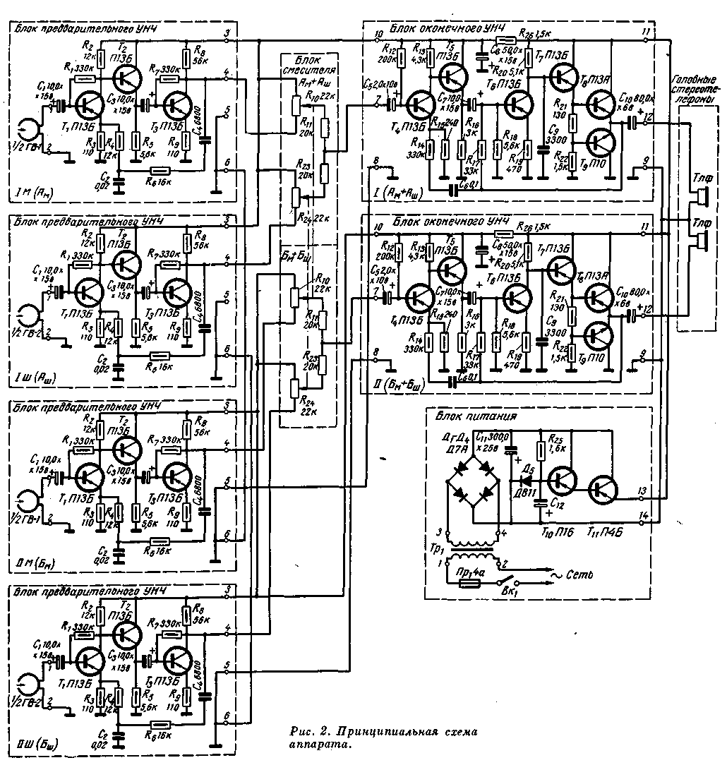
Frequency response correction in the bass preamplifier stage achieves high-quality reproduction in the frequency range up to 10 kHz. On fig. 2 shows a schematic diagram of a sound analyzer. All four signals are taken by magnetic heads from the tracks of the magnetic tape, the signal voltage is fed to the corresponding LF preamplifier, made on transistors T1-T3. Two LF preamplifiers amplify the music channel signals (Am and Bm), and the other two amplify the noise channel signals Bsh). At the input of the final bass amplifier, with the help of passive mixers (R10, R11, R23 and R24), music and noise are mixed in the required ratios. After mixing and amplifying the signal voltage by two terminal LF amplifiers (T4-T9), the signals Ash + Am are fed to one of the headphones, and Bsh + Bm to the other, resulting in a binatural effect. If necessary, the patient can separately adjust the level of music and noise from zero to maximum.
The three-stage LF preamplifier is made on transistors T1-T3 (P13B). The amplifier is covered by a frequency-dependent negative feedback with a depth of 19 dB. The first stage of the amplifier is made according to the scheme with a common emitter. The playback head is connected to the input of the amplifier through the capacitor C1. The transistor used in the first stage must have a minimum noise level. To match the first stage with the next, an emitter follower is used, which is galvanically connected to the first stage. The third stage is similar to the first. The negative feedback voltage is supplied from the collector circuit of the last transistor (T3) to the emitter circuit of the first one through the elements C4R4R6. The output stage is loaded on the level controller, which is located in the remote block - the mixer. The mixer block, designed as a separate remote control, is a rheostat divider consisting of two paired potentiometers (R10 and R24) and decoupling resistors R11R23. Potentiometers act as music and noise level controls. Decoupling resistors are needed to eliminate the mutual influence of the outputs of the LF preamplifiers. The resistance of these resistors is selected experimentally. The final amplifier increases the signal level to the level necessary for normal playback in headphones. This amplifier should have low harmonic distortion, high input impedance, low voltage gain and additional correction of the frequency response in the low-frequency region (approximately 4 dB per octave). The final amplifier is assembled on six transistors (T4-T9), five of which are of the p-n-p type, and the sixth (T9) is of the n-p-n type (P10). The first and third stages, made on transistors T4 and T6 according to a common emitter circuit, amplify the signal voltage. The second and fourth stages on transistors T5 and T7, (according to the emitter follower circuit) serve to match the output resistances of the previous stages with the input resistances of the subsequent ones. The output stage is a push-pull power amplifier, assembled according to a common collector circuit on transistors of different conductivity. This eliminates the need for a phase-inverted stage. The amplifier is covered by deep feedback (26 dB), which dramatically reduces the coefficient of non-linear distortion. The feedback voltage is frequency dependent (frequency dependent feedback), which results in additional correction of the frequency response of the playback channel in the low frequency region. In addition, the input impedance of the final amplifier covered by the feedback is increased. The amplifier is not critical to the load. The power supply unit of the device contains a voltage stabilizer on T10T11 transistors. The reference voltage is removed from the silicon zener diode type D811. The rectifier is assembled according to the bridge circuit on four D7A germanium diodes. The entire device is powered by AC power through a power transformer. The kinematic scheme of the tape drive mechanism is shown in fig. 3. The use of an endless loop of a magnetic tape placed in a special cassette made it possible to simplify the tape drive mechanism and use a low-power EDG-1M type motor.
The cassette of the device is a plastic box with a roll of tape 230 m long, which is wound on a disk base, freely rotating on the axis of the cassette. The working diameter of the drive shaft is 5 mm. Thanks to the use of an endless tape loop, there is no need to rewind, and the device is always ready for action. The tape drive mechanism is driven by a toggle switch that turns on the power to the motor and presses the drive roller against the shaft. Two stereo heads are located directly under the cassette body. For reliable contact of the magnetic tape with the heads, a special felt clamp is used, which is removed at the moment the device is turned on. Structurally, the entire apparatus is made in the form of a separate unit (Fig. 4). The weight of the apparatus is 5 kg. Its dimensions are 230X150X105 mm. The top cover is removable.
A cassette with a device for installing and pressing a magnetic tape to the shaft, two stereo heads and an on/off toggle switch are fixed on the top panel of the device (Fig. 5). The stereo heads are covered with a safety cap.
Under the panel is a board made of V-95 alloy 6 mm thick. A tape drive mechanism is fixed on it, which includes an electric motor of the EDG-1M type, a flywheel with a drive shaft, control and clamping rods (Fig. 6). On the same board, the entire electronic part is fixed, consisting of a four-channel playback amplifier, power supply, power transformer and connecting blocks.
The playback preamplifiers are made in the form of a separate unit. It is mounted on a box-shaped steel chassis. Chassis dimensions 160x80x40 mm. All four amplifiers are assembled on textolite boards and separated from each other by screens (Fig. 5). The final amplifiers are assembled on two textolite boards and are located on the other side of the mounting of the preamplifiers. The control panel is made in the form of a separate unit. This unit includes two dual potentiometers that act as level controls, and output blocks for connecting doctor and patient headphones. Authors: P. Weinboim, G. Mironenko; Publication: N. Bolshakov, rf.atnn.ru
Machine for thinning flowers in gardens
02.05.2024 Advanced Infrared Microscope
02.05.2024 Air trap for insects
01.05.2024
▪ SanDisk Z410 Solid State Drives ▪ People need to leave the Earth
▪ section of the site Labor protection. Selection of articles ▪ article Mind, honor and conscience of our era. Popular expression ▪ article What is mica? Detailed answer ▪ Article Long motor life. Personal transport ▪ article Microbeetle for FM band. Encyclopedia of radio electronics and electrical engineering
Home page | Library | Articles | Website map | Site Reviews
www.diagram.com.ua |


 Leave your comment on this article: