|
|


 Arabic
 Bengali
 Chinese
 English
 French
 German
 Hebrew
 Hindi
Hindi Italian
 Japanese
 Korean
 Malay
Malay Polish
 Portuguese
 Spanish
 Turkish
 Ukrainian
 Vietnamese
|
ENCYCLOPEDIA OF RADIO ELECTRONICS AND ELECTRICAL ENGINEERING Generator on PIC16F84A and AD9850. Encyclopedia of radio electronics and electrical engineering
Encyclopedia of radio electronics and electrical engineering / Microcontrollers Measuring generators, in which the required frequency value is set using the keyboard, are known to readers of the journal (see, for example, the article by A. Piskaev "Frequency meter-generator-clock" in Radio, 2002, No. 7, pp. 31, 32). As a rule, these devices are made on a microcontroller, the range of generated frequencies is limited to several megahertz, and it is impossible to obtain an accurate frequency value. The generator described in the article also contains a microcontroller, but it is used only to control a specialized microcircuit - the AD9850 frequency synthesizer. The use of this microcircuit made it possible to expand the range of generated frequencies from fractions of a hertz to 60 MHz, within which any frequency value can be obtained with an accuracy of 1 Hz. The proposed oscillator is based on the AD9850 chip from Analog Devices, which is a complete DDS (Direct Digital Synthesis) frequency synthesizer with a built-in comparator. Such synthesizers are unique in their accuracy, are practically not subject to temperature drift and aging (the only element that has instability inherent in analog devices is a digital-to-analog converter). Due to the high technical characteristics of DDS synthesizers, they have recently replaced conventional analog frequency synthesizers. Their main advantage is the very high frequency and phase resolution, which are controlled digitally. The digital interface makes it easy to realize microcontroller control. A more detailed description of the principles of direct digital frequency synthesis can be found, for example, in [1]. The block diagram of the AD9850 synthesizer is shown in Figure 1.
Its basis is the phase accumulator that forms the code of the instantaneous phase of the output signal. This code is converted into a digital value of a sinusoidal signal, which is converted to analog with the help of a DAC and filtered. The comparator produces a square wave output signal. Its frequency fout (in hertz) is determined by the formula fout = Δfin/232, where fin is the clock frequency, Hz; Δ - 32-bit frequency code value. The maximum value of fout cannot exceed half the clock frequency. AD9850 Key Specifications (at 5V supply voltage)
The AD9850 provides both parallel and serial interfaces for downloading data. In the latter case, data (a 40-bit word) is input through its input D7. Each data bit is accompanied by a positive polarity pulse at the clock input W_CLK. After the control word is loaded by a pulse of positive polarity at the FQ_UD input, the generation parameters are replaced with new ones. The assignment of bits of the control word is given in Table. 1.
Schematic diagram of the generator is shown in fig. 2. Manages the synthesizer DD2 microcontroller DD1.
It polls the SB1-SB16 keyboard, displays information on the HG1 LCD indicator, calculates the frequency code value and transmits it via a serial interface to the DD2 synthesizer. The sound emitter HA1 is used to confirm pressing the keyboard buttons. Chip AD9850 (DD2) is used in the standard inclusion [2]. At the output of its DAC, the Z1 filter is turned on. After the filter, a sinusoidal signal is fed to the XW2 socket and to the input of the comparator of the DD2 chip (pin 16). From the output of the latter, a rectangular signal is fed to the XW1 socket. The G1 crystal oscillator is used as a clock generator for DDS. Trimmer resistor R7 adjust the contrast of the image on the indicator HG1. After resetting the microcontroller, the HG1 LCD indicator is set to the 4-bit bus exchange mode, which is necessary to reduce the number of I / O lines required to write information. The generator is controlled using a keyboard consisting of buttons SB1-SB16. Since all port B input lines are connected to the power supply through resistors, there is no need for external resistors to "pull up" the RB4-RB7 ports to the power line. Resistors R3-R6 protect the outputs of the microcontroller from overload when several buttons are accidentally pressed at the same time. The required frequency is set from the keyboard. To do this, by pressing the buttons with the corresponding numbers, enter the desired value (in hertz) and press the "*" button. If the frequency does not exceed the maximum allowable, the message "OK" appears on the indicator for a short time and the generator goes into operating mode, and if it exceeds, the message "Error" appears. In this case, you need to press the "C" ("Reset") button and re-type the correct value. The same is done in case of an error in the process of entering the frequency. Pressing this button twice puts the device into operating mode with the previously set frequency value. In operating mode, an asterisk symbol flashes in the rightmost familiarity of the indicator. If the current frequency value is entered from an external control unit (for example, from a computer), then to return to the frequency displayed on the indicator, just press the "*" button. Buttons "U" (Up - up) and "D" (Down - down) allow you to step change the output frequency of the generator, respectively increasing or decreasing the value of the decimal place by one. The desired decimal place is selected by moving the cursor with the "L" (Left - left) and "R" (Right - right) buttons. When the "*" button is pressed, the frequency value and the cursor position are stored in the non-volatile memory of the microcontroller, so that the interrupted operation mode is automatically restored the next time the power is turned on. Since the computational capabilities of the microcontroller are limited, the output frequency value is set with an accuracy of about 1 Hz, which is sufficient for most cases. To fully realize the possibilities of the synthesizer, it can be controlled using a PC. To do this, the generator must be modified by supplementing it with a node, the diagram of which is shown in Fig. 3. PC (or other control device) is connected to socket XS1. At a low logic level at the address inputs A, the multiplexers of the DD3 chip connect the synthesizer control inputs to the DD1 microcontroller, and at a high logic level, to an external device. The control signals are received via the "ENABLE" contact of the XS1 socket. Resistor R19 provides a low logic level at the address inputs DD3 when the control device is not connected.
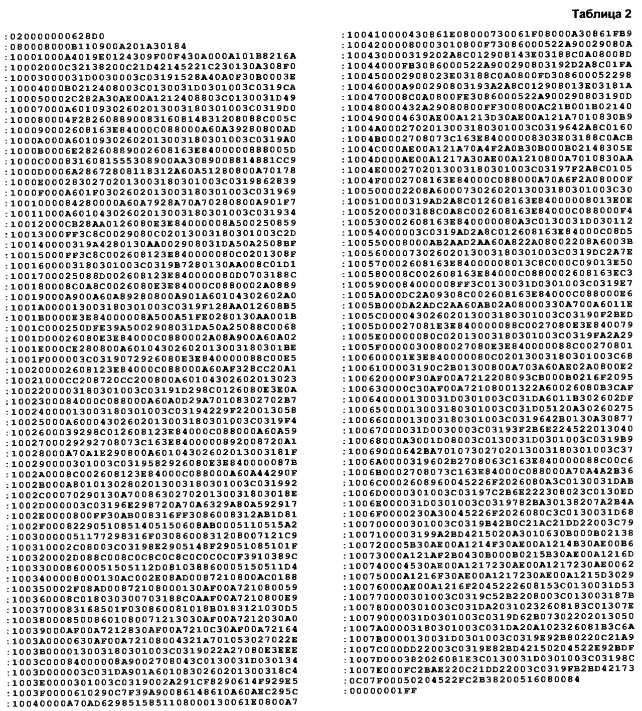
The generator is assembled and tested on a breadboard. If it is not possible to purchase a board for the SSOP package for the DD2 microcircuit, you can use short (10 ... 15 mm long) pieces of tinned wire with a diameter of 0,2 mm to connect its outputs to the corresponding pads. Conclusions 1,2,5,10,19, 24, 26,27, 28 are connected to a common wire with one segment of a greater length. LCD indicator HG1 - ITM1601 (16-character one-line with built-in controller). HA1 - any piezoelectric sound emitter with a built-in generator, designed for a voltage of 5 V. As a clock generator (G1), you can use a micro-assembly of a quartz oscillator for a frequency of up to 125 MHz, it is permissible to use a similar unit with quartz stabilization and on discrete elements. The control program of the microcontroller depends on the frequency of the clock generator. "Firmware" for the most common values Program codes for a generator with a frequency of 32 MHz are given in Table. 2.
When programming the microcontroller, the following bit values are set in the configuration word: oscillator type (OSC) - RC, watchdog timer (WDT) - disabled, post-power-on delay (PWRTE) - enabled. Literature
Author: S.Kuleshov, Kurgan
Artificial leather for touch emulation
15.04.2024 Petgugu Global cat litter
15.04.2024 The attractiveness of caring men
14.04.2024
▪ Philips BDM4UP 3275K monitor with MultiView ▪ Trees will help find the bodies of people missing in the forest ▪ Computer mouse without borders
▪ section of the site Amateur Radio Technologies. Selection of articles ▪ Article Prevention of drug addiction. Basics of safe life ▪ article What invention of Edison is used every day? Detailed answer ▪ article Nightshade bittersweet. Legends, cultivation, methods of application ▪ article VHF-FM tuner. Encyclopedia of radio electronics and electrical engineering ▪ article Transistors foreign. Encyclopedia of radio electronics and electrical engineering
Home page | Library | Articles | Website map | Site Reviews
www.diagram.com.ua |


 Leave your comment on this article: