|
|
Chip TDA8362 in 3USCT and other TVs. Part 3. Encyclopedia of radio electronics and electrical engineering
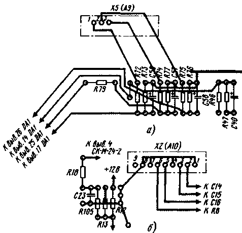
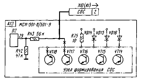
Encyclopedia of radio electronics and electrical engineering / Телевидение Installing the MRCC in ULPCT TVs is quite simple: you need to remove the DBK and BC blocks and place the MRCC instead of the BRK, making small changes in other blocks. Such a replacement leads to a very effective result - two of the three most bulky TV units have been eliminated, power consumption has been significantly reduced, and the number of radio tubes has been more than halved. All this significantly improves the temperature regime in the TV case - its "Achilles heel", the main cause of frequent fires. Instead of the connectors indicated in the previously considered diagrams, a Sh15 socket is installed on the MRCC board and cables are connected to the Sh2a, Sh7a, Sh15a plugs to supply the necessary voltages and signals. The Sh9 cable connecting the DBK with the BC is removed as unnecessary. Instead of a tube ultrasonic frequency converter, the UM1-3 module from UPIMCT should be used. The SK-M-15 drum selector used in the TV, which has a very low gain Ku (8 dB), is replaced by SK-M-24, SK-D-24 or a more modern one with a UVP installation of the USU-1-15 or MSN type -501. A significant reduction in the current consumption for all supply voltages requires the selection of the values of the quenching resistors in the collector unit in order to return to the standard nominal voltages. The +12 V voltage in the ULPCT is formed in the control unit from the +24 V voltage with a stabilizer from a quenching resistor and a D814B zener diode. This node is too weak to power the MRCC and must be replaced with a unit designed for a higher current. If the owner of the upgraded TV satisfies the previously adopted module parameters - accept only SECAM and PAL systems, standards B and G in the ZUSCT TV with selectors SK-M-24-2, SK-D-24, then it is possible to assemble the MRCC without any changes according to the previously discussed circuit diagrams. The printed circuit board of the module is shown in fig.12.a и fig.12.b It is suitable for any type of UVP with the following caveat. When using MCH-501, all printed conductors shown in fig. 12, a and b with solid and dashed lines, as well as all the details, except for the resistor R78. When using UVP types USU, SVP, printed conductors shown by dashed lines are not made, and parts VD1, VD5-VD7, R35, R81-R84, C23, X7 connector (A13) are not installed. Connector X10 (A13) is replaced with X5 (A9). The changes that must be made on the printed circuit board are shown in Fig. 13, a: resistors R46, R47, R79 and capacitor C40 are placed in the same way as in fig. 12, a. Capacitors C57-C59 are placed in a new way, together with resistors R72-77. Connector X2 (A13) is replaced by connector X2 (A10). At the same time, its contacts 2, 3, 5, 6 are switched on in the same way as contacts 3-6 of connector X2 (A13), as shown in fig. 13.b. If you want to use any of the modifications listed above, it is useful to draw up a complete schematic diagram of the future module based on the previously considered diagrams and recommendations, selecting the necessary elements from them. Then make the necessary changes to the printed circuit board of the module (in the pattern of printed conductors). Module parts are placed on a board made of double-sided foil fiberglass 2 mm thick. The tracing of the printed conductors of the module is made taking into account the placement of the leads of the parts in the grid nodes of 2,5x2,5 mm and the reduced distance between the leads of the TDA8362 chip (1,778 instead of the usual 2,5 mm). This forced the latter to be displayed on both sides of the board. In the detailed description of the TDA8362 chip [1], which you should get acquainted with, the need to ensure the minimum length of conductors between pins 28, 29 of the TDA8362 chip and pins 11, 12 of the TDA4661 chip, as well as from the common wire (pin 9 of the TDA8362 chip) is especially emphasized to the capacitors connected to its pins 12, 33, 42. Pin 3 of the TDA4661 chip (common wire of its digital part) and the pin of capacitor C32, connected to a common wire, with a separate conductor ("digital ground"), connect to pin 5 of connector X4 (A3 ). The module uses channel selectors removed from the RTO board of the TV being upgraded. Resistors - MLT with ratings according to the E24 series and a tolerance of ± 5%. All adjusting resistors - SPZ-38b. Capacitors up to 0,22 microfarads - ceramic K10-7 or K10-176 with an operating voltage of at least 16 V and a tolerance of ± 20%. Capacitors C7, C9, C56-C59, C73 with a capacity of 1 ... 10 microfarads - tantalum K53-3, K53-34, K53-35, the rest with a capacity of 1 ... 470 microfarads - oxide K50-6, K50-16, K50 -35. Capacitors C41, C45, C49 - ceramic KD-1, KD-2, KM-3 or glass-ceramic K21-8, K21-9 for a voltage of at least 250 V. Capacitors C44, C48, C52 - ceramic K10-47 or polyethylene refthalate K73-17, K73-24, K73-30 with a voltage of at least 250 V. Coils L1, L2, L4 - EC-24; 13 - circuit 11 or L2 from SMRK-2. The TDA8362 chip can be replaced by its full analog TDA8362N3; TDA8395 - chip TDA8395P or ILA8395; TDA4661 - TDA4665, TDA4660 microcircuits. When using the latter, a MLT-13 resistor with a nominal value of 0,125 MΩ is additionally connected to its output 1, connected by the second output to a common wire. The voltage synthesizer MSN-501, MSN-501-4 is connected to the module sockets with their standard connectors, without changes in their pinouts. Depending on the location of the MCH in the TV cabinet, it may be necessary to lengthen the connecting cables. Synthesizers MSN-501-8, MSN-501-9 can be used after a slight alteration. The SOS signal in these models is fed to the microcontroller not from pin 2 of the X10 (A1) connector, as for MSN-501, MSN-501-4, but from its own formation unit, assembled on transistors VT14-VT18. Changes are made to the synthesizer according to the scheme in Fig. 14. Transistors VT14-VT18 are no longer required. To disconnect them from the power supply circuits and outputs, the resistor R75 (10 Ohm) and diodes VD14-VD16 (KD521B) should be soldered. Resistors R42. R43 should be replaced with new ones with ratings of 620 and 510 kOhm, respectively. The output of the resistor R43 is connected with a wire to a free socket 2 of the plug of the X10 connector (A1). The numbering of parts is given according to the factory scheme of the TV set "Horizon - CTV518".
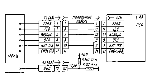
It is recommended to set up the module in the following order. Check and, if necessary, adjust the voltage at the outputs of the power module and the TV setting for the received programs when the APCG system is turned off. Check the power supply circuit of the module with an ohmmeter. The resistance of the +220 V circuit with respect to the common wire should be about 500 kOhm, the +12 V circuit - more than 750 Ohms, the +8 V and 5,6 V circuits - 700 and 600 Ohms, respectively. With these and further measurements, the polarity of the ohmmeter should be strictly observed. Remove the back wall of the TV, place the MRCC on the table next to the TV. Keeping all the TV modules in place, disconnect the cables X2 (A10), X9 (A9) from the MRK TV unit and connect to the MRKTs. If the TV uses an MCH synthesizer, these will be X2 (A13), X9 (A9) connectors. Put on the socket of the adjustment cable, assembled according to the scheme shown in fig. 4. The plug of this cable is plugged into socket X3N of the PSP board (A15). To contact 1 of the plug of connector X3 (A10) are connected shown in fig. 5 resistors R3, R15 to temporarily apply a voltage of +301 V to pin 302 of the DA2,5 chip. The remaining connectors will be connected to the MRCC later. Remove the channel selectors from the MRK unit, install them on the MRKTs board, connect the antenna.
Literature
Author: V. Brylov, Moscow; Publication: N. Bolshakov, rf.atnn.ru
Alcohol content of warm beer
07.05.2024 Major risk factor for gambling addiction
07.05.2024 Traffic noise delays the growth of chicks
06.05.2024
▪ Created the most powerful magnet in the world ▪ Transcend DDR4 Memory Modules for PCs and Servers
▪ section of the site Consumer Electronics. Selection of articles ▪ article by Michel de Montaigne. Famous aphorisms ▪ article Where does a train run that you can hitchhike at any point on its route? Detailed answer ▪ article Water supply in the Arctic. Travel Tips
Home page | Library | Articles | Website map | Site Reviews www.diagram.com.ua |


 Arabic
 Bengali
 Chinese
 English
 French
 German
 Hebrew
 Hindi
Hindi Italian
 Japanese
 Korean
 Malay
Malay Polish
 Portuguese
 Spanish
 Turkish
 Ukrainian
 Vietnamese


 Leave your comment on this article: