|
|


 Arabic
 Bengali
 Chinese
 English
 French
 German
 Hebrew
 Hindi
Hindi Italian
 Japanese
 Korean
 Malay
Malay Polish
 Portuguese
 Spanish
 Turkish
 Ukrainian
 Vietnamese
|
ENCYCLOPEDIA OF RADIO ELECTRONICS AND ELECTRICAL ENGINEERING Homemade miniature LED base lamp. Encyclopedia of radio electronics and electrical engineering
Encyclopedia of radio electronics and electrical engineering / Lighting The proposed device turns a flashlight, designed to install an incandescent lamp, into an LED. It doesn't require any modifications. In a homemade lamp, a base from an incandescent lamp was used. It has a super-bright LED and a pulse boost voltage converter. Super bright LEDs are reliable and durable. They are gradually replacing incandescent lamps in all applications, even street lamps and car lamps. And indeed, super-bright LEDs have taken a truly "royal" place in wearable miniature light sources - flashlights. Such devices have a design that allows you to replace only the batteries, since the replacement of LEDs is not provided due to their high reliability. However, many lanterns remained with a cartridge for a replaceable incandescent lamp. The article [1] tells about the conversion of such a lamp into an LED one. The article [2] describes the installation of one white LED in the base of an incandescent lamp. When developing the proposed device, the task was to create a structure based on the base of a miniature incandescent lamp with a step-up voltage converter inside it, and a super-bright LED outside. Such a device (a homemade LED base lamp) can be inserted into the lamp socket, as a result of which the lamp lamp will become LED without any alterations.
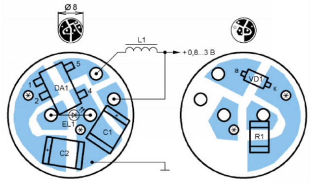
The scheme of the proposed device is shown in fig. 1. It contains an EL1 LED, a current-limiting resistor R1 and a voltage boost converter on a DA1 chip, an L1 inductor, a VD1 diode and capacitors C1 and C2. The converter is assembled according to a typical scheme on the NCP1400ASN33T1 (DA1) chip. The technical documentation for this chip is available on the manufacturer's website [3]. This chip starts at an input voltage of 0,8 V or more and maintains a stable output voltage of 3,3 V when the input drops to 0,2 V.
The device is mounted on a printed circuit board (Fig. 2) of a round shape with a diameter of 8 mm from fiberglass laminate with a thickness of 1,2 mm foiled on both sides. A chamfer of 0,2 ... 0,3 mm was removed along the perimeter of the board on both sides to avoid shorting the printed conductors of the board to the base during operation. After chamfering, holes are drilled in the board. Then the printed conductors are etched and tinned. When mounting parts, the author used an MBS microscope with a 10.15-fold magnification. Watch magnifiers can also be used, but it is desirable that their magnification be at least five times. For soldering elements, it is better to sharpen the tip of the soldering iron with a sharp cone. For example, for a tip with a diameter of 4 mm, a conical sharpening about 10 mm long is convenient. Insert pieces of wire into vias marked with asterisks and solder them on both sides. Next, mount capacitors C1 and C2. Remove the unused pin 3 of the DA1 chip, otherwise it will cover the board hole into which the anode pin of the EL1 LED should be inserted. Install the DA1 chip on the board. On the other side of the board, a VD1 diode is mounted. Resistor R1 is recommended to be installed later, after its selection. Next, mount the inductor L1. One output is inserted into the hole and soldered to the conductors of the board on both sides, the other output must be connected to the central contact of the lamp base - the positive power output. A flexible insulated wire is soldered to this terminal, connecting it to the printed circuit conductor of the board, going to the positive terminal of the capacitor C1. The leads of the EL1 LED are inserted into the holes, observing the polarity. The housing of the LED can touch the DA1 chip or rise above the printed circuit board to a height of up to 4 mm. From the bottom side of the board, the LED leads are soldered and cut off. A wire about a centimeter long is soldered to the connection point of capacitors C1 and C2. This is the negative power terminal that must be connected to the base. Next, select the current-limiting resistor R1. Instead, a variable resistor with a resistance of 50.100 ohms is temporarily switched on as a rheostat. Set its engine to maximum resistance. In series with the EL1 LED, a milliammeter with a measurement limit of 100 mA is turned on. A maximum supply voltage of 1,5 or 3 V is supplied, depending on how many galvanic cells are supposed to be used to power the device. By reducing the resistance of the variable resistor, set the desired brightness of the EL1 LED, without exceeding the maximum allowable current through it and the maximum allowable output current of the DA1 chip (100 mA). The author set the current to 20 mA. Next, turn off the circuit of a series-connected variable resistor with a milliammeter and measure its resistance. Then take a size 0603 or 0805 resistor of the same or slightly higher resistance and install it on the PCB as R1. Capacitors C1, C2 and the Schottky diode VD1 were dismantled from the board of a faulty Siemens AP75 mobile phone. The inductance of the inductor L1 is 18.27 μH. The length of its body should not exceed 5 mm. A standard EC24-220K series choke with a nominal inductance of 22 µH is used. LED EL1 - any super-bright white, 5 mm in diameter, for example, domestic KIPD80E20 or foreign 3R5, C503C, LC503TWN1. The glow color for flashlights is more often chosen as white, but by and large it depends on the preferences of the user. To increase reliability during operation, the printed circuit board with parts, except for the EL1 LED, is placed in an electrically insulating case made of a heat-shrinkable tube. It is made from a piece of such a tube with a diameter of 6 mm and a length of about 5 mm. This segment is stretched with round-nosed pliers to a diameter of approximately 9 mm, put on a printed circuit board and heated with a soldering iron for heat shrinking. Using a tube of a smaller diameter than the board allows you to get a thinner layer of insulation with sufficient reliability. All parts, together with the printed circuit board, are placed inside the base, in this example from a threaded lamp, but can also be placed in a pin (bayonet) base. The base is separated from the faulty incandescent lamp, for example, as described in article [2]. Prepare the lamp to remove the bulb, which does not always come out easily, can burst, scattering fragments, so protective measures must be taken when disassembling. To do this, a layer of plasticine with a thickness of at least 4 mm should be evenly applied to the flask. After making sure that the plasticine is securely attached to the flask, with pliers or a vice, slightly squeeze the base closer to the flask. Then relax the lips, turn the lamp 90 degrees and squeeze the base again. This will usually empty the flask. If not, repeat the operation. We remove the flask by unsoldering the lamp leads from the base. In the event that the flask has not separated, but burst, it is recommended to discard the base, since further operations with it will be dangerous. When the base is separated from the flask, you need to remove the remnants of heat-resistant glue from it. Then heat the end contact with a soldering iron and clean the solder hole in it from the inside, for example, with a wooden toothpick. The board with the parts is inserted into the base so that the L1 inductor output, left according to the diagram, comes out through the end contact hole of the base, then solder it, leaving a hemisphere of solder for better contact. The negative wire is bent over the upper edge of the base and soldered to it. It turned out a homemade miniature LED base lamp. To increase the reliability of operation in extreme conditions, it is advisable to pour an epoxy compound inside the base.
From one galvanic cell, the lamp consumes a current of 84 mA. The lamp works from any battery, including standard size LR44, as shown in fig. 3. A homemade LED lamp can be installed in a lamp with a cartridge that matches its base. The lamp can operate from one or two batteries with a total voltage of up to 3 V. It has not been tested on a larger number of batteries, since in this case an increase in voltage is no longer required. If there are empty spaces in the battery compartment of the flashlight, conductive overall dummies are inserted into them instead of batteries. Before the first installation, it is necessary to check the polarity of the supply voltage supplied to the lamp. Plus should be applied to the end contact, minus to the base. Literature
Author: N. Salekhetdinov
A New Way to Control and Manipulate Optical Signals
05.05.2024 Primium Seneca keyboard
05.05.2024 The world's tallest astronomical observatory opened
04.05.2024
▪ CoolSiC 1200V Silicon Carbide MOSFETs in TO247-3/-4 Package ▪ Clouds predict an earthquake ▪ Photosynthetic engine for artificial cells
▪ section of the site Electrician's Handbook. Article selection ▪ article A book with seven seals. Popular expression ▪ article In what country are phalluses depicted on the walls of many houses? Detailed answer ▪ Article Device for dismantling crankshafts. Personal transport ▪ article Fulfillment of desires with the help of a match. Focus secret
Home page | Library | Articles | Website map | Site Reviews
www.diagram.com.ua |


 Leave your comment on this article: