|
|


 Arabic
 Bengali
 Chinese
 English
 French
 German
 Hebrew
 Hindi
Hindi Italian
 Japanese
 Korean
 Malay
Malay Polish
 Portuguese
 Spanish
 Turkish
 Ukrainian
 Vietnamese
|
ENCYCLOPEDIA OF RADIO ELECTRONICS AND ELECTRICAL ENGINEERING Street lighting control device. Encyclopedia of radio electronics and electrical engineering
Encyclopedia of radio electronics and electrical engineering / Lighting There are many designs of automata that turn on street lighting at night and turn it off at dawn. However, as a rule, they are poorly protected from false alarms when the illumination fluctuates near the threshold during transitions from "day" to "night" and vice versa. In the proposed device, this problem is successfully solved. The automaton is assembled on several standard CMOS microcircuits of an average degree of integration.
The scheme of the proposed device is shown in fig. 1. When the power is turned on at input 9 of element DD1 3, using capacitor C5, a short pulse of a high logic level is generated, setting the RS flip-flop from elements DD1.3 and DD1.4 to a state with a high voltage level at the output of element DD1.4. Entering through the resistor R12 to the base of the transistor VT5, this voltage opens the transistor. As a result, the HL3 LED turns on, and the blocking oscillator on the VT4 transistor and the T2 pulse transformer starts to work. The pulses it generates open the VS1 triac, which turns on the EL1 lamp. The device is in this state until the other input of the RS flip-flop (pin 13 of the DD1.4 element) receives a pulse that will put the trigger in the opposite state, turn off the HL3 LED and stop the blocking generator. In the absence of pulses on the control electrode, the triac VS1 will stop opening, the EL1 lamp will go out If the external illumination is large enough ("day"), the resistance of its sensor, the photodiode VD1, is relatively low and the logic level at the inputs of the element DD1.1 is high. At the output of this element and at the input R of the counter DD4, the level is low, than the operation of this counter is allowed. LED HL1 "Night" off. The output of the element DD1.2 is high, so the HL2 "Day" LED is on, and the counter DD3 is disabled. The CN inputs of both counters receive pulses with a period of 60 s (1 min), generated by the "clock" chip DD2. Therefore, the counter whose operation is enabled (in this case, DD4) changes its state every minute, setting a high logic level on the next output and low on all the others. 4 minutes after the device is turned on, a high level will be set at pin 10 of the DD4 counter and at the input 13 of the DD1.4 element connected to it, which will turn off the EL1 lamp. In the future (in the daytime), the pulses at the output of the counter DD4 are repeated every 10 minutes. Therefore, if you turn on the lamp by pressing the SB1 button, which will bring the RS-trigger to the corresponding state, it will be automatically extinguished no later than 10 minutes later. With the onset of darkness, the resistance of the VD1 LED will increase significantly. The levels at the inputs and outputs of the elements DD1.1, DD1.2 will change to the opposite. As a result, the HL2 LED will be off, and HL1 will be on. At the same time, the operation of the DD4 counter will be disabled, and the DD3 counter will be enabled. If this state remains unchanged for 4 minutes, a high-level pulse will be generated at the output 10 of the counter DD3, which will go through the diode VD3 to the input 9 of the element DD1.3. This will change the state of the RS flip-flop and the EL1 lamp will be turned on. The lamp will automatically turn off when the illumination of the VD1 LED increases again and remains so for at least 4 minutes. Practice shows that such a delay in turning on and off the lamp is quite enough to prevent false alarms of the machine in case of significant, but relatively short-term changes in illumination under the influence of moving clouds, lightning flashes, illumination of the sensor by car headlights. The duration of the delay (both on and off) can be changed within 1-9 minutes by connecting the inputs of the RS-trigger with other outputs of the counters DD3 and DD4. If this has to be done frequently, switches can be provided in the machine. The power supply unit of the machine is built according to the classical transformer circuit with a voltage stabilizer on a VD4 zener diode and a VT3 transistor. The use of a stabilizer can be abandoned if the voltage in the supply network is not subject to significant fluctuations.
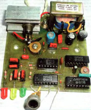
All elements of the machine are placed on the printed circuit board shown in Fig. 2 made of fiberglass laminated on one side. Its dimensions are chosen based on the placement in a plastic electrical junction box purchased at a hardware store. LEDs HL1-HL3 are soldered directly to the board, but if desired, they can be placed on the case panel. The SB1 button with normally open contacts is located on this panel. The appearance of the board with the circuit elements placed on it is shown in Fig. 3. The VD1 photodiode is placed outside the board and installed on the outer panel of the device.
KT315G transistors can be replaced with other silicon low-power npn structures. Chips of the K176 series (with the exception of K176IE18) can be replaced with similar K561 series or imported CMOS series: K176LE5 - CD4001, K176IE8 - CD4017. Chip K176IE18 can be replaced by K176IE12. In this case, the jumper connecting pin 14 of the DD2 chip with a common wire is not installed. Since an accurate timing is not required in this device, instead of a tuning capacitor C2, you can install a constant ceramic capacitance of 10 ... 20 pF. When switching lamps with a total power of up to 200 W, the TS112-10-7 triac (it can be replaced by the KU208G triac) is installed on an aluminum heat sink with an area of 15 ... 20 cm2 fixed on the board. This is sufficient when the power of the EL1 lamp or a group of incandescent lamps connected in parallel is not more than 200 watts. To control lamps with a higher total power (maximum 2000 W), the heat sink area will have to be increased accordingly, placing it not on the device’s printed circuit board, but in another place.
With a slight change in the control scheme shown in Fig. 4, not a triac can be used in the machine, but an ordinary asymmetric trinistor KU202M or KU202N The magnetic circuit of the pulse transformer T2 is a ring ferrite of the K10x6x5 size. The author used a "ring" from a faulty electronic ballast for energy-saving lighting lamps. The windings I, II and III of the transformer have 50, 25 and 30 turns, respectively, wound with a PEV-2 wire with a diameter of 0,15 mm. To ensure reliable opening of the triac, it may be necessary to select the number of turns of winding III. You can use any power transformer T1 that is suitable in size and has a secondary winding with a voltage of 10 ... 12 V at a load current of at least 50 mA. The author used a small-sized transformer with two secondary windings of 12 V each, designed for a current of 200 mA (one of them is not used). The machine does not have a separate switch and is connected directly to the 220 V network in the junction box or by a cord with a plug to a regular mains socket. It is not required to adjust the device; in the absence of errors in the installation, it starts working immediately after being connected to the network. The device is installed so that the VD1 LED is well lit by natural light. However, it must not be exposed to the light of the EL1 lamp. Otherwise, at night, the EL1 lamp will turn on and off with a period of 8 minutes. This can be used to check the functionality of the machine. For outdoor installation, the body of the machine must be carefully sealed to prevent dew, rain, snow, dust and dirt from getting inside. When installing the main unit indoors, the light sensor (LED VD1) can be taken out of it at a distance of up to several meters and connected to the printed circuit board with a shielded wire. The braid of this wire is connected to the plus of the supply voltage of the microcircuits. One of the variants of the described device was mounted inside a spotlight fixed above the entrance of a five-story building, and has been successfully operating for more than a year. Author: A. Zabarov
Machine for thinning flowers in gardens
02.05.2024 Advanced Infrared Microscope
02.05.2024 Air trap for insects
01.05.2024
▪ Tibet to build gravitational wave detector ▪ The author's fee will depend on the pages read ▪ ASUS RT-AC3200 3200 Mbps Router ▪ Liquid metal that autonomously changes its structure ▪ Building material from plastic waste
▪ section of the site Instructions for use. Article selection ▪ article And he - only anthill surprises his. Popular expression ▪ article What is Plasma? Detailed answer ▪ Kozelets article. Legends, cultivation, methods of application ▪ article DC power supply safety switch. Encyclopedia of radio electronics and electrical engineering
Home page | Library | Articles | Website map | Site Reviews
www.diagram.com.ua |


 Leave your comment on this article: