|
|


 Arabic
 Bengali
 Chinese
 English
 French
 German
 Hebrew
 Hindi
Hindi Italian
 Japanese
 Korean
 Malay
Malay Polish
 Portuguese
 Spanish
 Turkish
 Ukrainian
 Vietnamese
|
ENCYCLOPEDIA OF RADIO ELECTRONICS AND ELECTRICAL ENGINEERING Three-channel color and music console with compressors. Encyclopedia of radio electronics and electrical engineering
Encyclopedia of radio electronics and electrical engineering / Color and music installations, garlands The principle of operation of the proposed attachment is somewhat different from similar devices. Although it still has the frequency range of 3H input signals divided into three sections, each of which has its own color channel, the channel lamps connected in garlands flash in stages - depending on the input signal level. Therefore, not only the intensity of illumination of the set-top box screen changes, but also the area of the illuminated area. As a result, a wide variety of configurations of color combinations are "drawn" on the screen. As practice has shown, the aesthetic perception of the color accompaniment of musical works increases with such work of the set-top box. Schematic diagram of the attachment is shown in fig. one.
It has a 3H preamplifier and three active filters: low (LF), medium (MF) and high (HF) frequencies. Each filter is followed by a so-called compressor, which "compresses" the dynamic range of the reproduced sound signal, and after it, a voltage amplifier that controls the operation of the screen lighting lamps. The pre-amplifier, designed to operate from a signal taken from the line output of a mono or stereo tape recorder or electrophone, is assembled on transistors VT1 and VT2. The input signal goes through the XS1 connector and resistors R1, R2 (they allow you to mix the left and right channel signals coming from a stereo sound reproducing device) to a common sensitivity control - a variable resistor R3. To increase the input resistance of the set-top box, the first stage of the amplifier is made on a field-effect transistor VT1 according to a common-source circuit. Resistor R5 sets the desired operating mode of the transistor. Capacitor C1 shunts this AC resistor so that the voltage gain of the stage does not decrease. Next, the signal is fed through the decoupling capacitor C2 to the input of the emitter follower, assembled on the transistor VT2. It has a relatively large input impedance and a low output impedance, which is necessary for better matching of the input stage with the frequency separation channels. The operation mode of the cascade is set by resistors R6-R8. From the resistor R8, the current and voltage amplified signal is fed through the decoupling capacitor C3 to the inputs of active filters made on composite transistors VT3VT4, VT6VT7 and VT9VT10. As you know, a composite transistor has a high transfer coefficient (approximately equal to the product of the transfer coefficients of both transistors), which means a large input resistance. This circumstance makes it possible to obtain a rather steep filter gain rolloff outside the passband. An RF filter is assembled on the VT3VT4 composite transistor, which passes signals with a frequency of more than 2000 Hz. The cutoff frequency is set by the value of the chain C4C5R10. The midrange filter on the transistor VT6VT7 passes signals with a frequency of 200 ... 2000 Hz. The lower cutoff frequency is determined by capacitors C 13, C 14 and resistor R23, and the upper one by capacitors C 11, C 12 and resistors R21, R22. The low-pass filter is made on a VT9VT10 transistor; it passes signals with a frequency of up to 200 Hz. The cutoff frequency is set by capacitors C20, C21 and resistors R34, R35. To match the dynamic range of the 3H signal (about 40 dB) with the brightness range of the screen illumination lamps (about 20 dB), there is a compressor after each active filter. It is a voltage amplifier (based on operational amplifiers DA1, DA3, DA5) with a logarithmic characteristic determined by the nonlinearity of the current-voltage characteristics of two diodes (VD1, VD2; VD6, VD7; VD11, VD12) connected in anti-parallel in the feedback circuit. The maximum compressor gain, say, on the DA1 chip, is determined by the ratio of the resistances of resistors R16 and R15 - it corresponds to compression of the dynamic range of the 3H signal by approximately 20 dB (10 times) when the signal at the compressor input changes from 5 to 500 mV (100 times). The signals from the outputs of the compressors are fed through isolation capacitors (C8, C 17, C25) to rectifiers assembled on diodes (VD3, VD4; VD8, VD9; VD13, VD14) according to the voltage doubling scheme. Capacitors C9, C18, C26 serve to smooth out the ripple of the rectified voltages that are released on the corresponding variable resistors (R17, R30, R42). From the resistor engines, the desired level of output voltage of the rectifiers is fed to the amplifiers, each of which consists of two stages - on the operational amplifier (DA2, DA4, DA6) and on the transistor (VT5, VT8, VT11). The overall gain of such a node is determined by the ratio of the resistances of the resistors, (for example, R19 and R18) in the feedback circuit. A diode (for example, VD5), shunting the emitter junction of the transistor, closes the feedback circuit of the operational amplifier. The amplified signals are fed to the output devices A1-A3, assembled according to the same schemes. On fig. 1, only the diagram of the node A1 of the higher frequency channel is disclosed. At its input, which receives a signal from the emitter of the transistor VT5, there is a threshold device assembled on diodes VD16 - VD24. Its operation is based on the property of a semiconductor diode to open at a certain voltage between the anode and cathode. So, for germanium diodes, this voltage is 0,2 ... 0,4 V, for silicon - 0,6 ... 0,8 V. The threshold device works like this. When the voltage at the input of node A1 rises to approximately 0,4 V, the key, made on the composite transistor VT12VT22, opens and lamps EL1, EL12 light up. A further increase in voltage leads to the opening of the diode VD16, and hence the key on the transistor VT13VT23. Flash lamps EL2, EL13. If the voltage continues to increase, the VD17 diode opens, the key on the VT14VT24 transistor, etc. In other words, the greater the control signal, the greater the number of channel lamps lights up. The lamps EL11, EL22 are constantly on and are intended for initial screen illumination. The set-top box is powered by a block containing a T1 transformer, two bridge rectifiers and two stabilizers. To power the incandescent lamps of the screen, a rectifier bridge on diodes VD27-VD30 is used. The VD31 rectifier bridge is used to power compensation voltage stabilizers, one of which is made on VT32-VT34 transistors and a VD25 zener diode, and the other on a VT34 transistor and a VD26 zener diode. The result is a bipolar voltage, which is necessary for the operation of operational amplifiers. Since the current consumed in the source circuit is 12 V, it significantly exceeds the current consumed from the second source, a composite transistor (VT32VT33) is used as a regulator in it. The set-top box uses fixed resistors MLT-0,25 (R56 and R57) and MLT-0,125 (the rest), variable resistors can be SP-1 or other similar ones. Oxide capacitors - K52-2 (C28-C31) and K50-6 (the rest), other permanent capacitors can be of the KT, KLS, KM, K73 series. Instead of K553UD2, you can use K553UD1A or similar operational amplifiers, for example, the K 140, K153 series with a supply voltage of ± 12 ... 15 V. Instead of MP26B transistors, any of the MP39-MP42 series will do; instead of KT315G - KT315B and KT315E; instead of KT361G - KT361B and KT361E; instead of GT403B - any of the GT403, P213, P214 series; instead of GT321V - any of the GT402, KT501, KT502 series; instead of KP103K - KP103L, KP103M. Diodes D223 can be replaced by any of the D220, KD521 series; D9G - any of the D9 series; D242 - any other with a permissible rectified current of 10 A. Powerful diodes should be placed on radiators with a total area of 40 ... 50 cm2, made of sheet copper or brass 2 ... 3 mm thick. The power transformer can be ready-made with a power of 60 ... 70 W. Its winding II must be rated for a voltage of 8 V at a load current of 8A, and winding III for a voltage of 30 V (between the extreme terminals) at a load current of up to 0,5 A. contain 20 turns of wire PEV-32 1200, winding II - 1 turns PEV-0,41 46, winding III - 1 turns with a tap from the middle of the wire PEV-0,8 174. All incandescent lamps - for a voltage of 3,5 V and a current of 0,26 A. Part of the details of nodes A1-A3 is mounted on three separate boards (Fig. 2) made of one-sided foil material, and most of the parts of the amplifiers, active filters and power supply are placed on a common board (Fig. 3) of the same material.
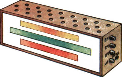
The power transformer, powerful diodes and boards are mounted in a case with dimensions of 560x220x140 mm (Fig. 4), the frame of which is made of metal corners 20x20 mm and sheathed with textolite 5 mm thick, except for the front panel - it is made of frosted organic glass. Ventilation holes are drilled in the upper wall of the case.
At a distance of about 20 mm from the front panel-screen, there is a panel made of fiberglass, in which incandescent lamps are fixed - they are located in accordance with Fig. 5.
In the top row there are high-frequency channel lamps, painted in yellow and orange, in the middle row - mid-range channel lamps (green and light green), in the bottom row - low-frequency channel lamps (red and crimson). Thus, three colored bands are formed, "flaring up" from the middle of the screen. When the signal level of the reproduced piece of music changes, the width of the luminous bands and their number change depending on the frequency spectrum of the signal. To get more complex shapes on the screen (circles, rectangles, stars, etc.), you will have to increase the number of incandescent lamps in each channel, placing them on the panel behind the screen accordingly. It is possible to increase the screen size and use more powerful lamps, even for a voltage of 220 V. In this embodiment, it is more expedient to use trinistor switches instead of transistor ones to control the ignition of lamps. During the operation of the set-top box, the most pleasant screen illumination is selected by variable sensitivity resistors for channels and overall sensitivity. Author: V.Demyanets
The existence of an entropy rule for quantum entanglement has been proven
09.05.2024 Mini air conditioner Sony Reon Pocket 5
09.05.2024 Energy from space for Starship
08.05.2024
▪ There are more microbes in a man's beard than in dog hair ▪ Fossilized unicellular can help find methane in the ocean
▪ site section Indicators, sensors, detectors. Article selection ▪ article by Galileo Galilei. Famous aphorisms ▪ article How do we measure the strength of earthquakes? Detailed answer ▪ video engineer article. Job description
Comments on the article: Valery I love electronics!
Home page | Library | Articles | Website map | Site Reviews
www.diagram.com.ua |


 Leave your comment on this article: