|
|


 Arabic
 Bengali
 Chinese
 English
 French
 German
 Hebrew
 Hindi
Hindi Italian
 Japanese
 Korean
 Malay
Malay Polish
 Portuguese
 Spanish
 Turkish
 Ukrainian
 Vietnamese
|
ENCYCLOPEDIA OF RADIO ELECTRONICS AND ELECTRICAL ENGINEERING Transistor converter at 144 MHz. Encyclopedia of radio electronics and electrical engineering
Encyclopedia of radio electronics and electrical engineering / radio reception The converter, which is described in this article, allows you to receive signals from amateur VHF radio stations in the range of 144-146 MHz. It is designed to work with a communication receiver having a range of 4-6 MHz. The converter is simple in design and easy to set up, and therefore can be easily repeated. It is intended mainly for work in the field. To power the converter, a voltage of 6 V at a current of 18 mA is required. The noise factor of the converter is 4,5-5 kTo, the design dimensions are 130x45x20 mm. The converter circuit is shown in fig. 1. In it, having implemented the current principle of constructing a resonant RF amplifier. An RF amplifier built according to this principle has a number of advantages over a conventional amplifier, since in the current control mode the amplifying properties of the transistor are more fully used, interstage matching connections are simplified and losses in them are reduced, and there is no need to use neutralization.
The RF amplifier is two-stage, assembled on transistors T1, T2. The collector current of the transistors is set equal to 3,5-4 mA, while achieving the lowest noise figure with a sufficiently high gain. The input circuit of the amplifier is formed by the inductance of the coil L1, the capacitance of the trimmer capacitor C1 and the input capacitance of the transistor. To achieve the minimum noise figure, the bandwidth of the input circuit is 6-10 MHz. The output capacitance of the transistor T1 together with the capacitance of the trimmer capacitor C4, the inductance of the coil L2 and the input capacitance of the transistor T2 form an interstage matching P-filter. The output P-filter of the second stage of the amplifier is similarly arranged. The tuning of the RF amplifier is carried out by tuned capacitors C4, C8, connected in parallel with the output capacitance of transistors T1, T2, however, it can also be done by changing the inductance of the coils L2, L8. During experimental verification, it was found that this two-stage RF amplifier, in the absence of a tendency to self-excitation, provides somewhat greater gain than a typical three-stage amplifier based on common-base transistors with autotransformer interstage coupling. The converter mixer is assembled on a T3 transistor according to a common emitter circuit. The amplified signal voltage is supplied to the base of the transistor T3 through the capacitor C9, and through the capacitor C11, the local oscillator voltage is also applied to it. The collector circuit includes a broadband circuit L4C13, tuned to a frequency of 5 MHz. The voltage of the IF signal from the coupling coil L5 is applied to the input KB of the receiver.
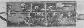
Converter local oscillator - two-stage. On the transistor T4, having assembled the master oscillator according to the "three-point" circuit with quartz in the positive feedback circuit. Quartz with a fundamental frequency of 11666 kHz is excited at the third mechanical harmonic. The L6C17C18 circuit in the collector circuit is tuned to a frequency of 35 MHz. A parametric frequency multiplier is assembled on the T5 transistor. The capacitance value of the collector-base junction of this transistor depends on the voltage applied to it. When a high-frequency signal is applied to the transistor input, the amplified voltage is applied to its collector junction and causes modulation of its nonlinear capacitance, which leads to parametric generation of harmonics. A transistor multiplier in this mode is equivalent to an amplifying stage followed by a varactor frequency multiplier. Such multipliers are simple and effective, especially when the output signal frequency exceeds the cutoff frequency of the transistor. An oscillatory system is included in the collector circuit of the transistor T5. It consists of a circuit tuned to 35 MHz - L8C20, and an associated circuit tuned to the output frequency - L9C23. To obtain maximum multiplication efficiency, the collector of transistor T5 is connected to part of the turns of coil L8 in such a way that the series circuit formed by part of the turns of L8 and capacitor C20 is tuned to a frequency close to the second harmonic - about 70 MHz. For good harmonic filtering, the L9C23 circuit must have as high a quality factor as possible. The converter is assembled on a chassis measuring 130x45x20 mm, made of silver-plated brass sheet 0,5 mm thick (see Fig. 2). The chassis is separated by well-soldered partitions separating the cascades from each other. Passing capacitors and insulators are installed in the partitions, blocking capacitors C3, C7, C12 are installed on the partitions. The installation was carried out by a hinged method in compliance with the specifics of the installation of VHF equipment. Particular attention should be paid to the minimum length of the leads of transistors, blocking capacitors, etc. The data of coils and chokes are given in the table. Frameless coils are wound with a pitch of 1 mm on a mandrel with a diameter of 8 mm, the rest are coil by coil. The tuning cores of the L6 and L8 coils are brass, with M4 thread, the L4 coils are ferrite. Establishing the converter begins with checking the installation and modes. Table 1
Collector currents are set for transistors T1, T2, equal to 3,5-4 mA, for T3, T4-2,5-3 mA. The collector current of the transistor T5 depends on the excitation voltage. By selecting the connection of the L7 coil with the L6 coil, with the master oscillator set, this current is set within 8-10 mA. Then the local oscillator circuits are tuned, temporarily turning on a capacitor with a capacity of 10-30 pF instead of quartz. The master oscillator should generate at a frequency of about 35 MHz. The frequency is checked by a wavemeter, a receiver, or a frequency meter. After that, quartz is turned on and, by changing the ratio of the capacitances of capacitors C17, C18, stable generation is achieved at the greatest detunings of the L6C17C18 circuit. Using a tube voltmeter and a standard signal generator, for example G4-7A, GZ-8A, tune the L9C23 circuit to a frequency of 140 MHz. By tuning the L8C20 circuit and selecting a tap from the L9 coil, the highest signal voltage with a frequency of 140 MHz is achieved when the excitation voltage multiplier is applied to the fetus from the master oscillator. If necessary, select the location of the outlet from the coil L8. The L4C13 circuit in the T3 collector circuit is tuned to an IF frequency of 5 MHz, the RF amplifier circuits to the middle frequency of the range - 145 MHz. The bandwidth of the amplifier from the antenna input to the base of the transistor T3 is 1,5-2,5 MHz. If an amateur has a noise generator at his disposal, then the local oscillator voltage should be selected. the current of the transistor T1, the coefficient of inclusion of the emitter T1 in the circuit L1C1, as well as an instance of the transistor T1 for the minimum noise figure. In conclusion, it should be said that using transistors with a high cut-off frequency (GT329, GT330 and others) can significantly reduce the noise figure. The principle of constructing a converter with such transistors may be different. Author: L. Rud (RB5LCE), Izyum; Publication: N. Bolshakov, rf.atnn.ru
Artificial leather for touch emulation
15.04.2024 Petgugu Global cat litter
15.04.2024 The attractiveness of caring men
14.04.2024
▪ Drinking hot drinks when it's hot ▪ Seagate BarraCuda 510 M.2 SSDs ▪ China's high-tech development ▪ Intel sold 1.000.000.000 processors in 25 years
▪ site section Electric motors. Article selection ▪ article by Sappho. Famous aphorisms ▪ article Can you really hypnotize a snake? Detailed answer ▪ article Sverbig oriental. Legends, cultivation, methods of application ▪ article Quartz chaotic oscillator. Encyclopedia of radio electronics and electrical engineering ▪ article Magic wand with coins. Focus secret
Home page | Library | Articles | Website map | Site Reviews
www.diagram.com.ua |


 Leave your comment on this article: