|
|


 Arabic
 Bengali
 Chinese
 English
 French
 German
 Hebrew
 Hindi
Hindi Italian
 Japanese
 Korean
 Malay
Malay Polish
 Portuguese
 Spanish
 Turkish
 Ukrainian
 Vietnamese
|
ENCYCLOPEDIA OF RADIO ELECTRONICS AND ELECTRICAL ENGINEERING The use of integrated circuits KF548XA1 and KF548XA2. Encyclopedia of radio electronics and electrical engineering
Encyclopedia of radio electronics and electrical engineering / Application of microcircuits On integrated circuits KF548XA1 and KF548XA2, it is possible to build a superheterodyne radio receiver with a minimum number of inductors (only in the input circuits), designed to receive programs from long-wave and medium-wave radio stations. Due to the absence of LC circuits, it can be performed using the hybrid integrated technology, which can significantly increase reliability, reduce weight and dimensions. A great advantage of the receiver is also its power supply from a low voltage source (3...6 V). The KF548XA2 microcircuit is a frequency converter, which includes a mixer, a local oscillator and a local oscillator supply voltage stabilizer. The need for a supply voltage stabilizer is due to the fact that due to the presence of parasitic capacitances of integrated transistors (collector - base ~ 1 pF and collector - substrate ~ 3 pF) at the maximum frequency of the local oscillator, made according to the RC oscillator circuit, - 2,5 .. 3 MHz, when the supply voltage changes by 1 V, its departure reaches 5 ... 7 kHz. Such a change in frequency in portable receivers is not always acceptable. A radical means of combating this shortcoming of RC generators is to stabilize the voltage of their supply circuits. Moreover, it is necessary to stabilize not only the supply voltage, but also the currents of the transistors. In the local oscillator of the KF548XA2 microcircuit, this is achieved by using direct current sources with a directly proportional dependence of the current on temperature. The local oscillator has no special outputs and is connected to a mixer inside the microcircuit. The mixer is made according to the classical scheme [1] of a balanced modulator and has four external outputs: an input signal is applied to two (11 and 14), a control signal to one (15) to adjust the gain when AGC is introduced at a high frequency, and from one (16) the output signal of the inverter is taken. The K548XA1 chip performs the functions of the IF path. It consists of second-order active RC filters (AF) connected between a variable current amplifier (CU) and an amplitude detector. Adjacent channel selectivity is provided by a piezoceramic filter included at the RF path input. The IF signal selected by him is fed to the input of the RU, the gain of which is adjusted by the AGC signal. The experiment showed that such a single-stage switchgear can provide a control range of 70 ... 80 dB, and there is no need to use several stages of switchgear, as is done, for example, in a similar-purpose K174XA2 microcircuit. Such an amplifier also has a low harmonic coefficient (0,5% over the entire control range with an amplitude modulation depth of 80%). The RU currents that change during the adjustment process are used to indicate fine tuning to the radio station. Moreover, the circuitry design of the switchgear allows you to install tuning indicators that work both at a minimum (LED) and at a maximum (pointer) readings. The maximum signal in the AGC circuit, and hence the fine tuning to the station, will correspond to the maximum current flowing through the microammeter connected to the collector circuit of the input transistor RU, and the minimum reading of the indicator installed in the collector circuit of the output transistor, i.e. connected in series with load resistor RU. The AF consists of three amplifiers, made according to the OK-OE scheme, and works as a selective current-voltage converter. Here are some parameters that characterize the effectiveness of the use of AF in the IF path. At a resonant frequency of 465 kHz and a quality factor of 12, the AF bandwidth of -3 dB is close to 40 kHz. The attenuation of the local oscillator signal with a frequency of 1,2 ... 1,5 MHz is approximately 40 dB, almost as much as a single bandpass LC circuit with a Q factor of 30 provides. The maximum gain of the IF path from the piezoceramic filter output to any AF output is ~ 2000 or 66 dB. In other words, a signal of 50 μV at the output of the piezoceramic filter will be amplified to a level of 100 mV, which is quite enough for its high-quality detection by the signal detector, as well as for the active operation of the AGC circuit. Full-wave detectors are transistor amplifier stages with combined collectors and emitters, with the output of the AM signal detector being the combined collectors. The advantage of such detectors is low radiation at frequencies that are multiples of the IF. This makes it possible to exclude components with an IF frequency from the output signal spectrum, which significantly reduces the probability of path self-excitation. The output signal of the AGC detector is fed to an amplifier, which also provides the necessary control signal delay and includes a simple low-pass filter. In a non-inductive IF path, the only potentially tuning block is the AF, operating at a frequency of 465 kHz. However, in most cases, it does not actually need to be configured. The following estimates can serve as a basis for such a conclusion. When using capacitors with a capacitance deviation from the nominal value of ±: 5% and resistors with a resistance deviation from the nominal value of ± 2%, the quality factor of the AF is set with an accuracy of about ± 10% for the worst case and about ± 5% for 95% of the samples with a normal deviation distribution law real parameters of the elements from the nominal ones. The inaccuracy of the resonant frequency setting has a more significant effect on the total frequency response of the filters. In the case under consideration, the deviation of the resonant frequency from the required one for the worst case will be ±7%, which corresponds to a loss in the IF path gain of less than 6 dB in the worst case and less than 3 dB for 95% of the samples. The attenuation of signals with a local oscillator frequency (1,2 ... 1,5 MHz) has practically no effect on the spread of resistances of resistors and capacitances of active filter capacitors. If necessary, it is easy to tune the AF to an intermediate frequency with any of the resistors connected between pins 1-14 or 16-13 of the microcircuit, or capacitors connected between its pins 1-16 and 13-15. The quality factor is adjusted by a resistor connected between pins 1-16.
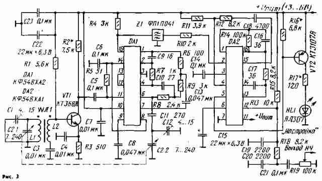
Typical circuits for switching on microcircuits KF548XA1 and KF548XA2 are shown in fig. 1 and 2. A medium-wave radio receiver built according to a typical scheme (Fig. 3) has the following main technical characteristics. Range of received frequencies, kHz ...... 510 ... 1640
We note some features of microcircuits that must be taken into account when building radio receivers. The sensitivity level of the KF548XA2 microcircuit is high, and the dynamic range of its mixer is limited. In this regard, it is not possible to satisfactorily match the magnetic antenna with the microcircuit without a preliminary matching amplifier. As such an amplifier, a cascade on a bipolar RF transistor (for example, KT368), connected according to a circuit with an OE, or a cascade with an RO on a field-effect transistor can be used. In the first case, the gain should be about 5, and the transformation ratio of the antenna circuit should be about 1:30. In the second case, the transformation ratio should be 1:2...1:3, or, somewhat worse, the input antenna circuit should be completely connected to the gate circuit of the matching amplifier transistor, after which the signal level should be reduced by 2...3 times. Further, the KF548XA1 microcircuit can be used with a pre-detector circuit. It should be connected between the input and output of the first AF amplifier (pins 1, 16), while its second amplifier is used as an inverter with a gain of 2 ... 4 kΩ between terminals 8,2 and 13).
The KF548XA1 microcircuit, together with the KF174PS1 microcircuit, makes it possible to create subminiature VHF receivers for model control systems. As an example, in fig. 4 shows a diagram of such a receiver. The main electrical parameters of the KF174PS1 microcircuit are given in [2].
Literature
Publication: N. Bolshakov, rf.atnn.ru
Machine for thinning flowers in gardens
02.05.2024 Advanced Infrared Microscope
02.05.2024 Air trap for insects
01.05.2024
▪ Inexpensive emulator for the C2000 DSP family ▪ NXP Opens Design Center in Singapore to Develop W-USB Technology ▪ Developed paper that turns heat into electricity
▪ site section Indicators, sensors, detectors. Article selection ▪ article Life on loan. Popular expression ▪ article How tall is a giraffe? Detailed answer ▪ article Washing and cleaning of machines and equipment. Standard instruction on labor protection ▪ article Prefix for testing transistors. Encyclopedia of radio electronics and electrical engineering
Home page | Library | Articles | Website map | Site Reviews
www.diagram.com.ua |


 Leave your comment on this article: