|
|


 Arabic
 Bengali
 Chinese
 English
 French
 German
 Hebrew
 Hindi
Hindi Italian
 Japanese
 Korean
 Malay
Malay Polish
 Portuguese
 Spanish
 Turkish
 Ukrainian
 Vietnamese
|
ENCYCLOPEDIA OF RADIO ELECTRONICS AND ELECTRICAL ENGINEERING Measuring microphone. Encyclopedia of radio electronics and electrical engineering
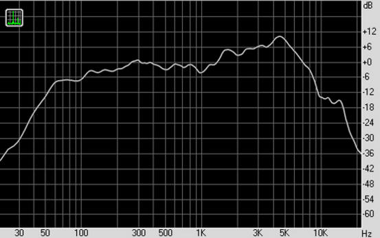
Encyclopedia of radio electronics and electrical engineering / Measuring technology One of the most important parameters of the speaker is its frequency response - the dependence of the sound pressure level in decibels on the frequency at a constant level of the supplied electrical signal. The wider the operating frequency range of the head or loudspeaker and the smaller the difference in sound pressure levels in different parts of this range, the better this electro-acoustic transducer. A visual representation of the frequency response gives a graphical representation (Fig. 1). As can be seen from this figure, there is a decrease in the sound pressure level at the lower and upper frequencies of the range, as well as a decrease and increase in the level ("rises" and "dips") at other frequencies.
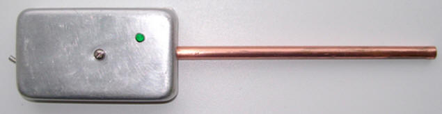
All these deviations of the sound pressure values can be the cause of the frequency distortions of the reproduced sound programs introduced by the loudspeaker [1]. Therefore, the frequency response of the heads is necessarily taken into account when designing acoustic systems, choosing speakers and the type of their acoustic design, calculating filters, etc. The data on the frequency response of the speaker, stated in the technical documentation (passport) and reference books are not unconditional. Each speaker has its own individual frequency response. At present, the time of the rapid development of digital technologies, it is not difficult to measure the frequency response of the sound pressure head of a dynamic head, even without the use of special equipment. To do this, you must have a personal computer, a low-frequency amplifier to excite the test head (computer audio system), a microphone and appropriate software. When measuring the frequency response of a loudspeaker, special requirements are placed on the microphone. It should have a wide frequency range, no narrower than 30 - 18000 Hz, a "smooth" frequency response, small membrane dimensions. Condenser microphones have the highest electroacoustic parameters, and this is their main advantage over other types of microphones. The frequency response of a condenser microphone is notable for its uniformity. In the range up to the resonance of the membrane, the unevenness can be very small, above the resonance it increases somewhat. Due to the small unevenness of the characteristics, condenser microphones are used as measuring ones. Measuring microphones are manufactured for the frequency range from 20 - 30 Hz to 30 - 40 kHz with an unevenness of 1 dB up to a frequency of 10 kHz and no more than 6 dB over 10 kHz. The dimensions of the capsule of such a microphone are taken in the aisles of 6 - 15 mm, because of this it is practically omnidirectional up to a frequency of 20 - 40 kHz. Its sensitivity does not exceed - 60 dB [2,3]. Microphone capsule Panasonic WM61 [4] is ideal for using it as a measurement. Connecting the capsule directly through the microphone input of the PC, using phantom power for its operation, is not recommended, because of the high probability of interference and noise, low sensitivity, which will negatively affect the quality of measurements. The microphone must be connected to the audio input of the motherboard, using a matching link - a microphone preamplifier. Making such a device with your own hands (Fig. 2) is not at all difficult. It consists of a microphone capsule with a diameter of 20 mm, placed in a tube, 6 cm long, a microphone amplifier based on an ORA2134 op amp, characterized by high performance [6], a chemical power source with a voltage of 9 volts, of the Krona type.
The electrical circuit diagram of the measuring microphone is taken from the source [6]. After some modifications, it has the form shown in Fig. 3. Capacitor C3 is replaced by a film capacitor (K-73, K-78 or another recommended for installation in the signal circuits of audio devices). Setting up an amplifier comes down to selecting an LED that would provide a voltage drop of up to 2 volts in the areas indicated in the diagram on the diagram.
The printed circuit board is made of foil fiberglass with dimensions of 55 x 20 mm - fig. 4. Designing and printing is done on PC using Sprint Layout 6.0 software.
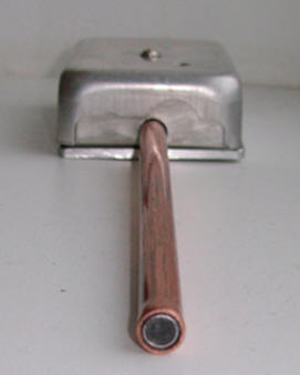
All this is mounted in a metal case - for shielding the circuit - fig. 5.
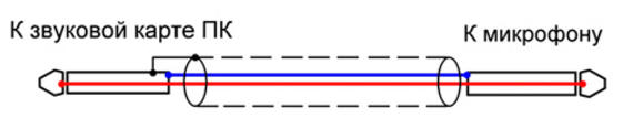
Connect the measuring microphone to the line input of the PC sound card via a shielded cable with two cores. The screen of the wire is connected on one side - the side of the sound card, this also has a positive effect on the accuracy of measurements - fig. 6.
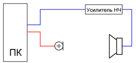
This design has a wide operating frequency range, relatively high sensitivity, flat frequency response, "hears" sounds at a greater distance, compared, for example, with the MKE-3 microphone. Measurements can be made from almost any distance audible to the human ear, and this is important when testing not only one head, but the entire acoustic system (s), for example, in a room or car interior. The microphone has been successfully tested with Right Mark 6.2.3. Shown in Fig. 1 graph of the frequency response of the sound pressure of the 25GDN-1L speaker built using this program. For measurements, the microphone is placed on the same axis with the head at a distance of 300 - 400 mm. Connection of measuring devices is carried out according to the scheme shown in fig. 7. It is important that the tone controls in the amplifier be in the middle position, and the loudness compensation mode and corrective links are disabled. The test head is placed farthest from walls, furniture and other objects [7].
Literature
Author: V. Marchenko
Air trap for insects
01.05.2024 The threat of space debris to the Earth's magnetic field
01.05.2024 Solidification of bulk substances
30.04.2024
▪ Brain chip to restore vision ▪ Fixed issue with lack of inspiration ▪ Xiaomi Lady Bei Portable Face Skin Humidifier
▪ site section Parameters of radio components. Article selection ▪ article In the seventh heaven (to be). Popular expression ▪ article What do the multi-colored rings on the Olympic flag mean? Detailed answer ▪ article Typesetter. Job description
Home page | Library | Articles | Website map | Site Reviews
www.diagram.com.ua |


 Leave your comment on this article: