Computer tester from the BM9222 MASTER KIT: troubleshooting in the PC system unit. Encyclopedia of radio electronics and electrical engineering

Encyclopedia of radio electronics and electrical engineering / Measuring technology
 Comments on the article
Computer tester VM9222 MASTER KIT, the appearance of which is shown in fig. 1 is used to diagnose malfunctions of personal computers such as the IBM PC or compatible with it [1].
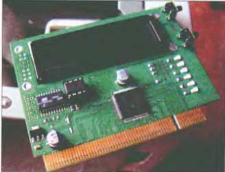
Fig. 1
The tester is a computer expansion board that is installed in any free PCI slot (33 MHz) of the motherboard. It is designed to display POST (Power-On Self-Test) codes generated by the computer BIOS in a user-friendly way.
Technical specifications
- Indication of POST codes: on the LCD display in two lines of 16 characters each (the first line is the POST code in hexadecimal form and separated by a dash is the BIOS type, the second line is a description of the error in the form of a running line).
- Indication of PCI bus signals: LEDs on the front side of the board - RST (PCI reset signal) and CLK (PCI clock signal).
- PCI bus supply voltage indicators: +5, +12, -12, +3,3 V.
- Compatible with motherboards based on INTEL, VIA, SIS chipsets.
- PCB size: 95,5x73,6mm.
Checking the PC system unit with a Post Card PCI tester
Checking the PC system unit using the Post Cord PCI tester includes the following steps:
- Processor testing.
- Checksum ROM BIOS.
- Checking and initializing DMA, IRQ and timer controllers. After this stage, sound diagnostics become available.
- Checking memory regeneration operations.
- Testing the first 64 kB of memory.
- Loading interrupt vectors.
- Video controller initialization. After this step, diagnostic messages are displayed on the screen.
- Testing the full amount of RAM.
- Keyboard testing.
- Testing CMOS memory.
- Initialization of COM and LPT ports.
- Initialization and test of the FDD controller.
- Initialization and test of the HDD controller.
- Search for additional ROM BIOS modules and initialize them.
- Calling the operating system loader (INT 19h, Bootstrap), if the operating system cannot be loaded, an attempt is made to start ROM BASIC (INT 18h); on failure - system halt (HALT).
Passage of tests
When passing each of the POST tests, a special code is generated, which is written to the diagnostic register. The information contained in the diagnostic register becomes available for observation when the POST Card diagnostic board is installed in a free slot of the computer and is displayed on a seven-segment display in the form of two hexadecimal digits. The address of the diagnostic register depends on the type of computer, in older versions it is: ISA, EISA-80h, ISA-Compaq-84h, ISA-PS/2-90h, MCA-PS/2-680h, 80h, some EISA-300h. Laptops can issue POST codes via LPT or USB port.
Before using the tester, you must determine the BIOS manufacturer of the motherboard. This can be done either by a sticker on the BIOS chip, or by the inscriptions that are displayed on the screen by a similar working motherboard. In Russia and the CIS, the most common are BIOS firms AMI and AWARD. With the acquisition of some experience, already by the first POST codes, you can confidently name the BIOS manufacturer.
POST code tables are different for different BIOS manufacturers and, due to the emergence of new tested devices and chipsets, they differ even for different versions of the same BIOS manufacturer.
Historically, the values of POST codes in the corresponding tables of BIOS manufacturers are given in hexadecimal form in the range OOh-FFh (0-255 in decimal), therefore, for the convenience of using such tables, it is necessary to ensure that POST codes are displayed in hexadecimal form.
In order not to make it difficult for readers to search for POST codes, the author gives them in a tabular form. According to the codes, you can draw a conclusion about a particular malfunction.
POST codes and their description
Here is a list of POST codes for troubleshooting (see table) on the example of a motherboard with BIOS from Award - AwardBIOS V4.51 PG Elite (see [2]).
In 1995, Award Software introduced a then-new low-level software solution, AwardBIOS "Elite", better known as V4.50PG. The checkpoint service mode has not changed in either the widespread version V4.51 or the rare version V4.60. The suffixes P and G denote, respectively, the support of the PnP mechanism and the maintenance of energy saving functions (Green Function).

Fig. 2
Consider the procedure for testing the system unit of a personal computer. After installing the tester in a free PCI-slot of the motherboard and turning on the PC power, the BIOS of the computer performs a serial poll of all devices included in the system unit (Fig. 2).
If all peripheral devices of the system unit are working, then after the download is completed, the inscription shown in fig. 3.

Fig. 3
If, however, various failures and errors occur during the operation of the PC, the tester displays the corresponding code. For example, in fig. Figure 4 shows a PC RAM error message.

Fig. 4
| POST code |
Description |
| Executing POST start procedures from ROM |
| WITH |
Disable External Cache. Disable Internal Cache. Shadow RAM ban. Programming DMA controller, interrupt controller, timer, RTC block |
| С1 |
Determining the type of memory, the total volume and placement by line |
| sz |
Verification of the first 256K DRAM for the organization of the Temporary Area. Unpacking BIOS in Temporary Area |
| С5 |
Executed POST code is transferred to Shadow |
| С6 |
Determining the presence, scope and type of External Cache |
| С8 |
Checking the integrity of programs and BIOS tables |
| CF |
Determining the type of processor |
| POSTing to Shadow RAM |
| 3 |
Disable NMI, PIE (Periodic Interrupt Enable), AIE (Alarm Interrupt Enable), UIE (Update Interrupt Enable). SQWV Programmable Frequency Generation Prohibition |
| 4 |
Checking the formation of requests for regeneration of DRAM |
| 5 |
Checking and initializing the keyboard controller |
| 6 |
Testing the area of memory starting at address FOOOh where the BIOS is located |
| 7 |
Checking CMOS and battery operation |
| BE |
Programming the configuration registers of the South and North Bridges |
| 9 |
Initializing L2 Cache and Cyrix Advanced Cache Control Registers |
| 0А |
Interrupt vector table generation. Configuring Power Management Resources and Installing the SMI Vector |
| OB |
CMOS checksum check. Scanning the bus PCI devices. Processor microcode update |
| OS |
Keyboard controller initialization |
| 0D |
Search and initialization of the video adapter. IOAPIC setup. Clock frequency measurements, FSB setting. |
| 0E |
MRS initialization. Video memory test. Display Award Logo |
| 0F |
Checking the first DMA 8237 controller. Keyboard detection and its internal test. BIOS checksum check |
| 10 |
Checking the second DMA 8237 controller |
| 11 |
Checking the page registers of DMA controllers |
| 14 |
System timer channel 2 test |
| 15 |
1st Interrupt Controller Request Masking Register Test |
| 16 |
2nd interrupt controller request masking register test |
| 19 |
NMI Passivity Check |
| 30 |
Determining the amount of Base Memory and Extended Memory Setting the APIC. Programmatic control of the Write Allocation mode |
| Preparing tables, arrays and structures to start the operating system |
| 31 |
The main on-screen test of RAM. USB Initialization The Plug and Play BIOS Extension splash screen is displayed. |
| 32 |
Setting up Super I/O resources. Programmable Onboard Audio Device |
| 39 |
Programming the clock generator on the 12C bus |
| ZS |
Setting the software flag to allow entry in Setup |
| 3D |
PS/2 mouse initialization |
| WE |
Initializing the External Cache Controller and Cache Permissions |
| BF |
Setting configuration registers chip set |
| 41 |
Initializing the floppy disk subsystem |
| 42 |
Disabling IRQ12 if no PS/2 mouse is present Performs a soft reset of the hard drive controller. Scanning other IDE devices |
| 43 |
Initializing Serial and Parallel Ports |
| 45 |
FPU coprocessor initialization |
| 4E |
Error message indication |
| 4F |
Request a password |
| 50 |
Restoring a previously saved CMOS state in RAM |
| 51 |
Allow 32 bit HDD access. configuring ISA/PnP resources |
| 52 |
Additional BIOS initialization. Setting PHX Configuration Registers Forming NMI and SMI |
| 53 |
Setting the DOS Time counter according to Real Time Clock |
| 60 |
Installing anti-virus protection BOOT Sector |
| 61 |
Final steps to initialize the chipset |
| 62 |
Read keyboard ID. Setting its parameters |
| 63 |
Correction of ESCD, DMI blocks. Clearing RAM |
| FF |
Transferring control to the bootloader. BIOS executes INT19h command |
Literature
- Description "Device for repair and testing of computers - POST Card PCI" BM9222.
- Award BIOS Error Codes - award.com.
- Magazine Repair and service
Publication: radioradar.net
 See other articles Section Measuring technology.
Read and write useful comments on this article.
<< Back
 Latest news of science and technology, new electronics:
The world's tallest astronomical observatory opened
04.05.2024
Exploring space and its mysteries is a task that attracts the attention of astronomers from all over the world. In the fresh air of the high mountains, far from city light pollution, the stars and planets reveal their secrets with greater clarity. A new page is opening in the history of astronomy with the opening of the world's highest astronomical observatory - the Atacama Observatory of the University of Tokyo. The Atacama Observatory, located at an altitude of 5640 meters above sea level, opens up new opportunities for astronomers in the study of space. This site has become the highest location for a ground-based telescope, providing researchers with a unique tool for studying infrared waves in the Universe. Although the high altitude location provides clearer skies and less interference from the atmosphere, building an observatory on a high mountain poses enormous difficulties and challenges. However, despite the difficulties, the new observatory opens up broad research prospects for astronomers. ... >>
Controlling objects using air currents
04.05.2024
The development of robotics continues to open up new prospects for us in the field of automation and control of various objects. Recently, Finnish scientists presented an innovative approach to controlling humanoid robots using air currents. This method promises to revolutionize the way objects are manipulated and open new horizons in the field of robotics. The idea of controlling objects using air currents is not new, but until recently, implementing such concepts remained a challenge. Finnish researchers have developed an innovative method that allows robots to manipulate objects using special air jets as "air fingers". The air flow control algorithm, developed by a team of specialists, is based on a thorough study of the movement of objects in the air flow. The air jet control system, carried out using special motors, allows you to direct objects without resorting to physical ... >>
Purebred dogs get sick no more often than purebred dogs
03.05.2024
Caring for the health of our pets is an important aspect of the life of every dog owner. However, there is a common assumption that purebred dogs are more susceptible to diseases compared to mixed dogs. New research led by researchers at the Texas School of Veterinary Medicine and Biomedical Sciences brings new perspective to this question. A study conducted by the Dog Aging Project (DAP) of more than 27 companion dogs found that purebred and mixed dogs were generally equally likely to experience various diseases. Although some breeds may be more susceptible to certain diseases, the overall diagnosis rate is virtually the same between both groups. The Dog Aging Project's chief veterinarian, Dr. Keith Creevy, notes that there are several well-known diseases that are more common in certain breeds of dogs, which supports the notion that purebred dogs are more susceptible to disease. ... >>
| Random news from the Archive Charging gadgets with vibration from walking
30.11.2022
Japanese scientists from Osaka Capital University announced the creation of a high-performance and compact vibration energy collector capable of charging gadgets worn by people while walking.
The size of the energy collector created by scientists is only 2 cm in diameter, the press service of the university reports.
It is noted that this development, called MEMS (microelectromechanical system with piezoelectric vibrational energy), is approximately 90 times more efficient than other similar developments.
The secret to this is the use of a U-shaped metal component called a dynamic magnifier that amplifies the vibrations that the MEMS converts into electricity.
The dynamic magnifier made it possible to improve the generation of electricity without increasing the size of the device.
MEMS is based on the use of the piezoelectric effect, a phenomenon in which certain types of materials produce an electrical charge or voltage in response to applied pressure.
|
Other interesting news:
▪ A battery the size of a grain of salt
▪ Canon EOS M10 Mirrorless Camera
▪ Highway with luminous markings
▪ Lefties do more
▪ By 2025, HDD capacity will grow to 100 TB
News feed of science and technology, new electronics
 Interesting materials of the Free Technical Library:
▪ section of the site Fundamentals of safe life (OBZhD). Article selection
▪ article International law. Crib
▪ article Descendants of which Columbia shuttle survivors were sent back into space? Detailed answer
▪ article The functional composition of Orson TVs. Directory
▪ article Connections of current sources. Encyclopedia of radio electronics and electrical engineering
▪ article Dream about the sky. physical experiment
Leave your comment on this article:
 All languages of this page
Home page | Library | Articles | Website map | Site Reviews

www.diagram.com.ua
2000-2024


 Arabic
 Bengali
 Chinese
 English
 French
 German
 Hebrew
 Hindi
Hindi Italian
 Japanese
 Korean
 Malay
Malay Polish
 Portuguese
 Spanish
 Turkish
 Ukrainian
 Vietnamese