|
|
ENCYCLOPEDIA OF RADIO ELECTRONICS AND ELECTRICAL ENGINEERING Prefix for measuring frequency characteristics. Encyclopedia of radio electronics and electrical engineering
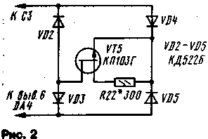
Encyclopedia of radio electronics and electrical engineering / Measuring technology Recently, visual methods of performance monitoring based on the use of panoramic indicators have been widely used in amateur radio practice. With their help, it is possible to much more quickly adjust such very complex radio engineering devices as filters, amplifiers, radios, televisions, antennas. However, it is not always possible to purchase such an industrial device, and it is not cheap. Meanwhile, without special costs, you can make a device similar in functionality in the form of an attachment to an oscilloscope. Such a prefix should contain a swept frequency generator (GCh), a voltage generator for sweeping the oscilloscope and a remote detector head. The scheme of such a prefix is shown in Fig. one. When developing the console, the goal was to create a simple, small-sized and easy-to-replicate design. True, due to its sheer simplicity, of course, it is not without some shortcomings, but it should be considered only as a basic design. As more nodes are added, it will be possible to expand the functionality and service convenience of the device. The proposed prefix is intended for tuning various electronic devices in the frequency range of 48 ... 230 MHz, i.e. in the MV television band. However, this design allows you to change the range of its operating frequencies, and then it will be able to operate in the UHF range (300 ... 900 MHz), the first intermediate frequency of satellite television (800 ... 1950 MHz) or on amateur radio KB bands. The main advantage of such a set-top box is that the entire frequency range is covered using one GKCh (this is convenient when setting up broadband devices, such as antenna amplifiers, TV channel selectors, etc.), it is possible to set the upper and lower frequencies of the swing range independently from each other with two control knobs. This allows you to quickly set the required section of the operating range. The disadvantages of the device include the non-linear dependence of the sweep voltage and the change in its amplitude when changing the operating frequency range. The prefix consists of a GKCH assembled on transistors VT2 VT3, a buffer amplifier on a transistor VT4. On the elements DA1, DA2, DA4,001, a triangular voltage generator is assembled, on a DA5 chip and a transistor VT1, a current stabilizer to power the GKCh, and on a DA3 chip, an amplifier voltage for the sweep of the oscilloscope. The RF generator is assembled according to the scheme of a multivibrator with an inductive load. Such a circuit solution made it possible to provide coverage of the entire range (frequency overlap factor of about 5) without switching the frequency-setting elements. This is achieved by changing the current through the transistors, while changing the parameters of their conductivity and diffusion capacitances, which makes it possible to vary the frequency of such a generator over a wide range. So, when the current changes from 50 to 1,5 mA, the frequency changes from 48 to 230 MHz. But to increase the frequency stability and the ability to control the RF generator, it should be powered by a current stabilizer. The control voltage for the current stabilizer is formed on the capacitor C3, amplified by the DA5 chip, and its output signal controls the current flowing through the transistor VT1 (and the RF generator transistors). Elements DA1, DA2, DM and DD1 provide periodic recharge of the capacitor. The recharge cycle depends on the positions sliders of resistors R2 and R4. The voltage supplied to the resistors is stabilized by the parametric stabilizer R1 VD1. DC amplifiers DA1 and DA2 act as voltage comparators - the drop voltage across resistor R14 is used as a reference, and the switching voltages are determined by the positions of resistors R2 and R4. In the initial state, the capacitor C3 is discharged, so the resistor R14 and the terminals of comparators 3 DA1 and 2 DA2 will have a voltage close to zero. In this case, the input R of the trigger DD1 will be a high logic level, and the output S will be low, respectively, the direct output of the trigger will be low, and the inverse - high. In this state, the output of the DA4 microcircuit will be 10 ... 11 V and the capacitor C3 will start charging through the resistor R11. Increasing the voltage on the capacitor leads to an increase in current through the RF generator and to a decrease in the generated frequency. When the voltage drop across the resistor R14 equals the voltage across the engine of the resistor R4, a low logic level will appear at the output of the comparator DA2, but the trigger state will not change and the capacitor charging process will continue. When the voltage on the resistor R14 increases to the voltage level on the engine of the resistor R2, a high logic level will appear at the output of the comparator DA1, the trigger state will change to the opposite, so the output of the DM microcircuit will have a voltage of -10 ... -11 V and the discharge of the capacitor C3 will begin. In this case, the comparator DA1 will switch to a state with a low logic level at the output, but the trigger will not be transferred and the capacitor C3 will continue to discharge. When the capacitor is discharged to the operation voltage of the comparator DA2, a high logic level will appear at its output, the trigger will switch, the output of the DA4 microcircuit will have a voltage of 10 ... 11 V - charging of the capacitor C3 will begin again. Thus, I changed the voltage on the engines of the resistors R2 and R4, you can change the voltages at the inputs of the comparators, between which the capacitor C3 is recharged, i.e. the range of change in the current flowing through the RF generator, and hence the range of change in its frequency. Since these voltages can be set independently of each other, an independent setting of the upper and lower frequencies of the generator sweep range is provided. A triangular voltage is formed on the capacitor C3, and not a sawtooth, as is usually the case in such devices. Therefore, the frequency of the GKCH is tuned up and down at the same speed. This made it possible to eliminate the backscattering device necessary in such cases, which, of course, simplifies the design. It should be noted that the linearity of the triangular voltage will be low, but quite satisfactory. If linearity is important, then in the capacitor charging circuit, instead of resistor R11, a current stabilizer should be included, made according to the circuit shown in Fig. 2.
The buffer amplifier on the VT4 transistor provides decoupling between the RF generator and the load, and also forms the required output voltage level: it is 1 mV at the XS100 output, and -2 mV at the XS10 output. To synchronize the sweep of the oscilloscope, the voltage drop across the resistor R14 was used, it is proportional to the change in frequency (since both are a function of the current through the generator transistors), but inversely - a higher voltage across the resistor corresponds to a lower frequency value. Therefore, it is fed to an inverting amplifier (IC DA3) with an adjustable transmission ratio. At its output, a voltage is generated to synchronize the sweep of the oscilloscope, which has a direct relationship between voltage and frequency. The amplitude of this voltage is set by resistor R10. All radio elements of the set-top box are located on the printed circuit board shown in Fig. 3. It is made of double-sided foil textolite. The side free from elements is left metallized and connected to the other side with foil along the perimeter of the board. This side is also the front panel of the device, and the parts are covered with a case, preferably a metal one.
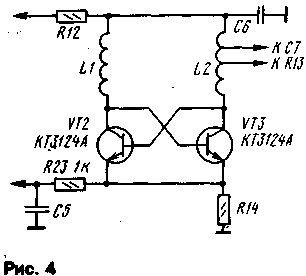
The following types of elements can be used in the device: OU - K140UD6 or K140UD7 (with letter indices A and B), digital microcircuit - K561TM2, 564TV1 or other microcircuits of the K561, 564 series containing an RS flip-flop. In addition, the trigger can also be assembled on the basis of the logic elements of the K561LA7, K561LE5 microcircuits, etc. Transistor VT1 - KT603 (with letter indices A - G); KT608 (A. B) KT630 (A, B), KT815 (A - D), KT817 (A - D); VT2 and VT3 -KT3123A, KT3123V, and with a decrease in the tuning range and KT363B, when using transistors KT3101A.KT3124A. KT3132A generator circuit must be changed in accordance with the diagram in fig. four; VT4 - KT4 (A, B), KT368A. KT399A, KT3101A or similar. Zener diode - KS147A, KS156A. Resistors R2, R4, R10 - SP, SPO, SP4-1, the rest - MLT. Capacitors C1.C3 - K50-6, K53-1, K52-1.S7-KD, KG, the rest - KM, KLS, KD. Jacks XS1, XS2 any high-frequency, for example television. Coils L1, L2 are frameless, wound on a mandrel with a diameter of 2 mm and contain 5 turns of wire with a diameter of 0,5 mm, winding length 15 mm.
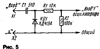
The diagram of the remote detector head is shown in fig. 5. It can use high-frequency detector diodes - KD419A, GD507A or similar. All elements are placed in the case from the felt-tip pen and the connections between them must have a minimum length. It is connected to the oscilloscope with a shielded wire. Establishing the device begins with an RF generator. To do this, the output of the resistor R11, which is lower in the circuit, is temporarily disconnected from the DA4 chip and connected to the engine of the resistor R2. A frequency meter is connected to the XS1 socket, then, by rotating the resistor R2, the frequency range of the generator is measured - its frequency overlap ratio must be at least 5. If so, then the range limits are set by simultaneously changing the number of turns of the coils or by compressing and unclenching the turns. If the overlap ratio turned out to be less, then you can try to increase it by reducing the value of the resistors R3 and R5 by 20 ... 30%. After that, all connections are restored and the operability of the triangular voltage generator is verified. To do this, control the voltage across the resistor R14 during the rotation of the resistors R2 and R4. Then the set-top box is connected to the oscilloscope and the horizontal sweep is set to the entire screen with the resistor R10. After that, a load (1 or 75 Ohm resistor) and a detector head are connected to the XS50 socket, and its output is connected to the "Input Y" of the oscilloscope. In this case, a curve should appear on the screen, reflecting the frequency dependence of the output voltage. By selecting the values of the elements C7, C10, R13 and the places where the latter are connected to L2, a voltage of about 100 mV is achieved with its unevenness of not more than 30%. In the author's design, the capacitor C7 was connected to the first, and the resistor R13 to the third turn of the coil L2, counting from the bottom according to the output circuit. In conclusion, the scales of the resistors R2 and R4 are calibrated. To do this, a signal from the reference generator is fed to the input of the detector head connected to the XS1 connector through a resistor with a resistance of 200 ... 300 Ohms. With a frequency of, for example, 100 MHz, and change its amplitude until a neat mark and curve is obtained. After that, with the "Fn" pen, the beginning of the sweep is combined with this mark and a mark is made on the scale. Then, with the "Fs" knob, align the end of the sweep with this mark and also make a mark already on the scale of this resistor. Similarly calibrate the scale for other frequencies. To power the set-top box, a bipolar stabilized power source was used, providing a current up to 100 mA through the positive shield and up to 10 mA through the negative one. Author:I. Nechaev, Kursk; Publication: N. Bolshakov, rf.atnn.ru
The world's tallest astronomical observatory opened
04.05.2024 Controlling objects using air currents
04.05.2024 Purebred dogs get sick no more often than purebred dogs
03.05.2024
▪ Charging gadgets with hot water
▪ section of the site Grounding and grounding. Selection of articles ▪ article Houses are new, but prejudices are old. Popular expression ▪ article How fast does our blood flow through the vessels? Detailed answer ▪ article Journalist of the department of creative programs. Job description
Home page | Library | Articles | Website map | Site Reviews www.diagram.com.ua |


 Arabic
 Bengali
 Chinese
 English
 French
 German
 Hebrew
 Hindi
Hindi Italian
 Japanese
 Korean
 Malay
Malay Polish
 Portuguese
 Spanish
 Turkish
 Ukrainian
 Vietnamese


 Leave your comment on this article: