|
|


 Arabic
 Bengali
 Chinese
 English
 French
 German
 Hebrew
 Hindi
Hindi Italian
 Japanese
 Korean
 Malay
Malay Polish
 Portuguese
 Spanish
 Turkish
 Ukrainian
 Vietnamese
|
ENCYCLOPEDIA OF RADIO ELECTRONICS AND ELECTRICAL ENGINEERING Electronic ballast for a DELUX compact fluorescent lamp. Encyclopedia of radio electronics and electrical engineering
Encyclopedia of radio electronics and electrical engineering / Lighting Although incandescent lamps are cheap, they consume a lot of electricity, so many countries refuse to produce them (USA, Western European countries). Instead, they come with compact fluorescent fluorescent lamps (energy-saving), they are screwed into the same E27 cartridges as incandescent lamps. However, they cost 15-30 times more expensive, but they last 6-8 times longer and consume 4 times less electricity, which determines their fate. The market is overflowing with a variety of such lamps, mostly made in China. One of these lamps, DELUX, is shown in the photo.
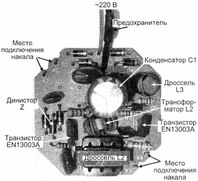
Its power is 26 W -220 V, and the power supply, also called electronic ballast, is located on a board measuring 48x48 mm (pic.1) and is located in the base of this lamp.
Its radio elements are placed on the circuit board by surface mounting, without the use of CHIP elements. The circuit diagram is drawn by the author from the inspection of the circuit board and is shown in Fig.2.
First, it is appropriate to recall the principle of ignition of fluorescent lamps, including the use of electronic ballasts. To ignite a fluorescent lamp, it is necessary to heat up its filaments and apply a voltage of 500 ... 1000 V, i.e. much higher than the mains voltage. The magnitude of the ignition voltage is directly proportional to the length of the glass bulb of the fluorescent lamp. Naturally, for short compact lamps it is less, and for long tubular lamps it is more. After ignition, the lamp sharply reduces its resistance, which means that a current limiter must be used to prevent a short circuit in the circuit. The electronic ballast circuit for a compact fluorescent lamp is a push-pull half-bridge voltage converter. First, the mains voltage is rectified to a constant voltage of 2 ... 300 V using a 310-half-wave bridge. The start of the converter is provided by a symmetrical dinistor, indicated in the diagram Z, it opens when, when the mains is turned on, the voltage at its connection points exceeds the response threshold. When opened, a pulse passes through the dinistor to the base of the lower transistor according to the circuit, and the converter starts up. Further, a push-pull half-bridge converter, the active elements of which are two npn transistors, converts a DC voltage of 300 ... 310 V into a high-frequency voltage, which can significantly reduce the size of the power supply. The load of the converter and at the same time its control element is a toroidal transformer (indicated in the L1 diagram) with its three windings, of which two control windings (each with two turns) and one working (9 turns). Transistor keys open out of phase from positive pulses from the control windings. For this, the control windings are included in the bases of the transistors in antiphase (in Fig. 2, the beginning of the windings are indicated by dots). Negative voltage surges from these windings are damped by diodes D5, D7. The opening of each key causes the induction of pulses in two opposite windings, including the working winding. Alternating voltage from the working winding is supplied to the fluorescent lamp through a series circuit consisting of: L3 - lamp filament -C5 (3,3 nF 1200 V) - lamp filament - C7 (47 nF / 400 V). The values of the inductances and capacitances of this circuit are chosen so that voltage resonance occurs in it at a constant converter frequency. At resonance of voltages in a series circuit, the inductive and capacitive resistances are equal, the current strength in the circuit is maximum, and the voltage on the reactive elements L and C can significantly exceed the applied voltage. The voltage drop on C5, in this series resonant circuit, is 14 times greater than on C7, since the capacitance of C5 is 14 times less and its capacitance is 14 times greater. Therefore, before the fluorescent lamp is ignited, the maximum current in the resonant circuit heats both filaments, and the large resonant voltage across the capacitor C5 (3,3 nF / 1200 V), connected in parallel with the lamp, ignites the lamp. Pay attention to the maximum allowable voltages on the capacitors C5 = 1200 V and C7 = 400 V. These values are not chosen by chance. At resonance, the voltage across C5 reaches about 1 kV and it must withstand it. A lit lamp sharply reduces its resistance and blocks (short-circuits) capacitor C5. Capacitance C5 is removed from the resonant circuit, and the voltage resonance in the circuit stops, but the already lit lamp continues to glow, and the inductor L2 limits the current in the lit lamp with its inductance. In this case, the converter continues to operate in automatic mode, without changing its frequency from the moment it was started. The entire ignition process takes less than 1 s. It should be noted that alternating voltage is constantly applied to the fluorescent lamp. This is better than constant, as it ensures uniform wear of the emissivity of the filaments and thus increases its service life. When lamps are powered by direct current, their service life is reduced by 50%, therefore, direct voltage is not supplied to gas-discharge lamps. Purpose of converter elements: The types of radio elements are indicated on the circuit diagram (Fig. 2).
Repair Before repairing the electronic ballast, it is necessary to "get" to its circuit board, for this it is enough to separate the two components of the base with a knife. When repairing a board under voltage, be careful, as its radio elements are under phase voltage! Burnout (break) of the dome spirals of a fluorescent lamp, while the electronic ballast remains intact. This is a typical error. It is impossible to restore the spiral, and glass fluorescent bulbs for such lamps are not sold separately. What is the way out? Or adapt a serviceable ballast to a 20-watt lamp with a straight glass lamp instead of its "native" choke (the lamp will work more reliably and without hum) or use the board elements as spare parts. Hence the recommendation: buy the same type of compact fluorescent lamps - it will be easier to repair. Cracks in the soldering of the circuit board. The reason for their appearance is periodic heating and subsequent, after turning off, cooling of the place of soldering. The place of soldering is heated from elements that are heated (spirals of a fluorescent lamp, transistor switches). Such cracks may appear after several years of operation, i.e. after repeated heating and cooling of the soldering place. The malfunction is eliminated by re-soldering the crack. Damage to individual radio elements. Individual radio elements can be damaged both from solder cracks and from power surges in the mains. Although there is a fuse in the circuit, it will not protect the radio elements from voltage surges, as a varistor could do. The fuse will burn out from breakdowns of radio elements. Of course, the weakest point of all the radio elements of this device are transistors. Author: N.P. Vlasyuk, Kyiv; Publication: cxem.net
Machine for thinning flowers in gardens
02.05.2024 Advanced Infrared Microscope
02.05.2024 Air trap for insects
01.05.2024
▪ Fairy robot for plant pollination ▪ Samsung steps up its work in the digital camera market ▪ World's largest XNUMXD printed building
▪ site section Infrared technology. Article selection ▪ article The case burned out for someone. Popular expression ▪ article How does the automatic control valve for space heating work? Detailed answer ▪ Berek's article. Legends, cultivation, methods of application ▪ article Simple five-element. Encyclopedia of radio electronics and electrical engineering
Comments on the article: Vladimir There is no point in the base of the trz-ra and D7 and the pinout of the trz-ra corresponds when the name is written on top.
Home page | Library | Articles | Website map | Site Reviews
www.diagram.com.ua |


 Leave your comment on this article: