|
|


 Arabic
 Bengali
 Chinese
 English
 French
 German
 Hebrew
 Hindi
Hindi Italian
 Japanese
 Korean
 Malay
Malay Polish
 Portuguese
 Spanish
 Turkish
 Ukrainian
 Vietnamese
|
ENCYCLOPEDIA OF RADIO ELECTRONICS AND ELECTRICAL ENGINEERING Soldering iron tip temperature regulator. Encyclopedia of radio electronics and electrical engineering
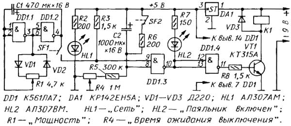
Encyclopedia of radio electronics and electrical engineering / Power regulators, thermometers, heat stabilizers This regulator differs from similar ones published in that it regulates (reduces) the thermal power of the soldering iron not by changing its supply voltage, but by interrupting the current through the heater for longer or shorter periods of time. Due to the significant thermal inertia of the soldering iron, after some time after changing the average power, it reaches a new stable tip temperature. In addition, the device provides automatic shutdown of the soldering iron if it is on the stand for a long time. The regulator is designed to work with a standard soldering iron. designed to operate on AC power. The soldering iron heater is connected to the network through a contact pair of an electromagnetic relay. With permanently closed contacts, the soldering iron operates in the rated power mode. If the relay winding is fed with DC pulses, the contacts will periodically open and close. Therefore, the average power released in the soldering iron heater will be less than the nominal one, and the less, the longer the open state of the relay contacts in relation to the closed time. The controller circuit is shown in Fig.1.
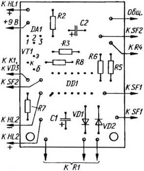
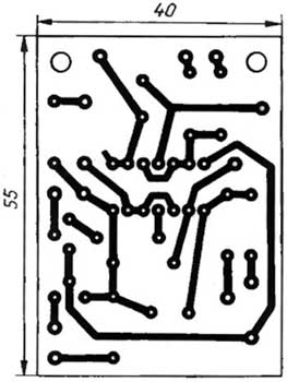
Relay K1 serves as the load of the current amplifier on the transistor VT1, powered by a voltage source of 9 V. Element DD1.4 inverts the output signal of element DD1.3. When the element DD1.3 is in the zero state, the HL2 LED "Soldering iron is on" is on, the transistor VT1 is open, so relay K1 is on and its contacts (they are not shown in the diagram) are closed - the soldering iron is warming up. A time relay is assembled on element DD1.3, capacitor C2 and resistors R4-R6. The SF2 contacts are mounted on the soldering iron stand. When the soldering iron is not on the stand, the SF2 contacts are closed, the capacitor C2 is discharged, both inputs of the DD1 3 element are high, and the output is low. So the soldering iron is on. If the soldering iron is placed on a stand, contacts SF2 will open under its weight and capacitor C2 will start charging through resistors R4, R5. After some time, depending on the resistance of the R4R5 circuit, the voltage across the capacitor C2 will increase so much that the element DD1.3 switches to a single state. The HL2 LED goes out, the transistor VT1 closes, the soldering iron turns off. On the elements DD1.1, DD1.2, a rectangular pulse generator is assembled, the duty cycle of which can be changed by a variable resistor R1. Contacts SF1 switch, combined with this variable resistor. If the SF1 contacts are closed, the voltage level at the lower input of the DD1.3 element according to the circuit will periodically change from low to high and back with the frequency of the generator. The frequency of the generator (about 0,5 Hz) when moving the engine of the variable resistor R1 remains almost constant. The duty cycle of the pulses (the ratio of the period of the pulse sequence to the duration of the pulses) theoretically varies from unity to infinity. In practice, due to the non-ideality of the diodes VD1, VD2, the variable resistor R1 and the logic elements of the DD1 microcircuit, the extreme values of the duty cycle do not reach either one or infinity. In other words, in one extreme position of the engine of the resistor R1, the soldering iron is turned on almost constantly, and in the other it is turned off. In intermediate positions of the engine, the relay is activated with each pulse and a power pulse from the network is supplied to the soldering iron heater. We note in passing that this method of regulation is called pulse-width (SHI). The regulator is assembled on a printed circuit board made of foil fiberglass with a thickness of 1 mm. The drawing of the board is shown in fig. 2
It is designed for the installation of MLT or BC resistors. Oxide capacitors - K50-35. The KR142EN5A stabilizer can be replaced with an imported 7805 or miniature 78L05, taking into account its pinout. Relay RES22, version RF4.523.023-01 or other, for an operating voltage of 9 ... 12 V, capable of operating at a voltage on the contacts of 220 V AC. Variable resistors R1 - SP3-48M, R4 - SP3-46M. The board is located at the base of the soldering iron stand. The regulator can be powered from a low-power rectifier built into the stand (it is not shown in the diagram) or from an external power supply. The SF2 switch is a contact group from any open type relay (REN, RKN, RKM, MKU, etc. series). The regulator does not require adjustment. If you need to change the limits for adjusting the exposure time of the soldering iron on the stand until it is turned off, you will have to select the resistor R5. Author: A. Krynitsky, Kazan; Publication: cxem.net
Machine for thinning flowers in gardens
02.05.2024 Advanced Infrared Microscope
02.05.2024 Air trap for insects
01.05.2024
▪ Cypress CYFB0072 4,8Gb/s video buffer chip ▪ Remains of ancient giants found ▪ New life for polyurethane waste
▪ section of the site Personal transport: land, water, air. Article selection ▪ article by Benjamin Johnson. Famous aphorisms ▪ article What films and albums were sold on pirated DVDs? Detailed answer ▪ Article Brand Manager. Job description ▪ article We catch microns. Encyclopedia of radio electronics and electrical engineering
Home page | Library | Articles | Website map | Site Reviews
www.diagram.com.ua |

 Leave your comment on this article: