|
|


 Arabic
 Bengali
 Chinese
 English
 French
 German
 Hebrew
 Hindi
Hindi Italian
 Japanese
 Korean
 Malay
Malay Polish
 Portuguese
 Spanish
 Turkish
 Ukrainian
 Vietnamese
|
ENCYCLOPEDIA OF RADIO ELECTRONICS AND ELECTRICAL ENGINEERING Touch control for lighting with remote control. Encyclopedia of radio electronics and electrical engineering
Encyclopedia of radio electronics and electrical engineering / Microcontrollers The proposed device is one of the options for microcontroller dimmers for incandescent lamps, the designs of which can be found on the Internet and in amateur radio literature. In such regulators, one of three control methods is usually used: from your own remote control; from any remote control with memorizing the key code; from any remote when pressing any key in a certain way. In this case, the first option is chosen, which I consider the most successful, despite the fact that a separate control panel is required. Let me explain a little why. Since different IR control systems have different modulation carrier frequencies, they can also differ in an arbitrarily used "remote-controller" pair, as a result of which the control range can be greatly reduced, which causes some inconvenience. The disadvantage of the latter method is also the fact that the regulator can respond to commands that are not intended for it at all, or regulation is difficult due to complex manipulations of the remote control key. The proposed regulator is controlled by two buttons of any remote control operating with the widely used RC-5 command system. The remotes of this system are quite affordable and cheap. Functions performed by the regulator:
Regulator control Manual (touch) control is carried out by touching the entire palm or four fingers of the sensor folded together without effort.
Remote control is carried out by the remote control directed towards the switch. To control the regulator, two keys of the remote control are defined.
The remote control button codes corresponding to these commands are stored in the EEPROM of the microcontroller. Thanks to this, in the learning mode (which is described in the manual), you can at any time change the set of remote control buttons that control the controller. Regulator device The regulator is built on an inexpensive and affordable microcontroller АТtiny2313-20SU. The schematic diagram of the device is shown below.
Power node consists of elements C2, R2, VD1, VD2, C3, C4 serves to provide the microcontroller and the IR receiver with a supply voltage close to 5 V. The R3C5 elements are a filter for the power supply circuit of the photodetector. Synchronization node. An input voltage divider is made on R4R6, which is necessary for detecting zero and eliminating false positives at the moments of opening VS1. C6 serves to suppress impulse noise. The output of the divider is connected to the output PD2. The internal diodes of this output of the MK limit the input voltage. Nodes of control and indication. On the elements R7, VT1, R8, C7, a touch control unit is implemented. When there is no hand on the sensor, VT1 is closed and a logic unit voltage is applied to the input PD4 of the microcontroller. When the regulator cover is touched, a logic zero voltage is applied to this input and the MK program processes the control commands.
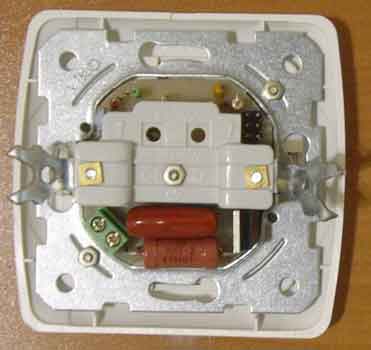
Switch node loads. From the output PB0 of the microcontroller DD1, negative pulses through R5 open the triac VS1 at various moments of the half-wave of the mains voltage and thus regulate the brightness of the lamp. The R1C1 circuit and the L1 choke are used to suppress interference coming from the regulator to the mains at the time of switching the load. Regulator design The regulator is assembled on a single-sided printed circuit board made of foil fiberglass, the drawing and location of the parts of which are in the attached files. The board is intended for installation in a VI-KO wall-mounted single-gang lighting switch (models "Yasemin" or "Carmen") from which unnecessary elements are removed and fastened to the frame with a d2.5mm screw. in the center. Under his hat, you need to put an insulating washer. On the reverse side, it is fixed with a nut as shown in the attached photo. The sensor in the form of a 30x45 mm rectangle cut out of foil is installed on the inside of the cover (which previously served as a key) and fixed on it with transparent tape over the entire area, it is only necessary to leave a contact pad for the spring. On the sides of the lid, strips of cardboard 4 mm x 30 mm in size and 0,5 mm thick are glued so that it sits in place with some effort. The piezo emitter is fixed on the cover with double-sided adhesive tape. The drawings in the attached files show the elements of the hull after completion. The regulator is placed in a standard recess for the switch in the wall and is connected according to the usual two-wire circuit, no modifications are required. It is necessary to connect the phase wire correctly, as shown in the diagram, otherwise the control from the sensor will not work. Appearance of the assembled device.
Used parts and possible replacements. To control the regulator, you can use any remote control that works according to the RC-5 protocol. We replace the DD1 microcontroller with an ATtiny2313-20SI or ATtiny2313V-20SU(SI), and the B1 photodetector with a similar one, designed for a carrier frequency of 36 kHz, for example, SFH506-36, TSOP1736, TSOP1836SS3V, but it should be noted that the location of the pins of photodetectors of different types may differ. As L1, an industrial surface-mount choke of the CDRH127 / LDNP-101MC PBF brand (100 μH 1,7A) was used. It can be replaced with a similar or home-made inductance of 30 - 200 μH for a current not less than the lamp consumed by the lamps (0,5 A for every 100 W). Symmetrical thyristor VS1 can be from the BT137 - BT139 series for a voltage of at least 400V or similar from another manufacturer with a low control current. We will replace the VD2 zener diode with 1N4734A, KS156A, KS456A. Instead of the HL1 LED indicated in the diagram, you can use HB3B-446ARA or similar super-bright red glow colors (if the brightness is not enough, you can reduce R14 to 4,7 com.). The piezo emitter can be replaced with a frameless type FML-34,7T-2,9V1-100 or any other similar three-wire so-called "self-driven", for example, a ringer from old telephone sets of Asian origin. Of course, it is easier to use a piezoelectric emitter with a built-in generator, for example HPA17A or HPM14A, but the author could not purchase such. In this case, the elements R10, R11, R12, R13, VT2 are not installed, and the sound emitter is connected to + 5V and to the PD0 terminal, observing the polarity. Instead of VT1, VT2, transistors of the KT315 (B, G, E), 2SC1015Y, KT3102 or similar types can be used. At the same time, the VT1 120 300. Capacitors C2, C200 type K1-2 or similar imported for a voltage not lower than those indicated in the diagram. All resistors - MLT power indicated on the diagram. The resistance ratio R73 / R17 must be close to 6 - otherwise the zero detector will not work correctly. Assembly and adjustment of the regulator An unmistakably assembled regulator from serviceable parts does not need to be adjusted. It is only necessary to program the microcontroller. The programmer is connected to the XP2 connector (a standard six-pin connector for in-circuit programming of AVR microcontrollers). In this case, the controller must be supplied with voltage from the programmer (the controller must be disconnected from the mains during programming) . The attached files contain two firmware: one implements only touch control, and the second - both types of control for 5 minutes. (Designed to test the device's performance). For full-featured firmware, please contact the author, alexperm72@mail.ru. The FUSE bits of the DD1 microcontroller must be programmed as follows: • CKSEL3...0 = 0100 - synchronization from the internal RC oscillator 8 MHz;
The instruction manual is in the attached files. The controller has a mode for checking the remote control for compatibility. To do this, you need to turn it on and set the minimum brightness, then press any button on the remote control and if it works according to the RC-5 system, then a beep will sound for 1 second. Permissible total power of switched lamps - 400 W. With a larger one, it is necessary to install a triac on a heat sink of the corresponding area. The regulator is designed to control only active load. Do not connect other devices, such as fluorescent lamps or electric motors, to it. This may damage the regulator. The regulator has good repeatability, all the assembled specimens started working immediately without any adjustment. When assembling and adjusting the regulator, remember that all its elements are under mains voltage and touching them can lead to electric shock. Download project files in one archive Author: Alexey Batalov, alexperm72@mail.ru, ICQ#: 477022759; Publication: mcuprojects.narod.ru/dimmerSIR/DimmerSIR.html
Machine for thinning flowers in gardens
02.05.2024 Advanced Infrared Microscope
02.05.2024 Air trap for insects
01.05.2024
▪ LT1990 Micro Power Differential Amplifier ▪ Harm of antibiotics and antiseptics ▪ World's smallest high-speed MOSFET ▪ Navigator looking for parking
▪ section of the site Car. Article selection ▪ article by Emil Michel Cioran. Famous aphorisms ▪ article What is the origin of the goldfish? Detailed answer ▪ article Removing and installing car wheels. Standard instruction on labor protection ▪ article What is Frame Relay? Encyclopedia of radio electronics and electrical engineering
Comments on the article: Leo I think it's an interesting scheme.
Home page | Library | Articles | Website map | Site Reviews
www.diagram.com.ua |


 Leave your comment on this article: