|
|


 Arabic
 Bengali
 Chinese
 English
 French
 German
 Hebrew
 Hindi
Hindi Italian
 Japanese
 Korean
 Malay
Malay Polish
 Portuguese
 Spanish
 Turkish
 Ukrainian
 Vietnamese
|
ENCYCLOPEDIA OF RADIO ELECTRONICS AND ELECTRICAL ENGINEERING Protection device for high-current equipment. Encyclopedia of radio electronics and electrical engineering
Encyclopedia of radio electronics and electrical engineering / Clocks, timers, relays, load switches The proposed device is designed to protect equipment that consumes a significant pulsed current from a DC voltage source (UMZCH, transceivers, etc.). The device disconnects the load in cases of excessive increase or decrease in supply voltage. The protection thresholds can be adjusted over a wide range. The small dimensions of the device allow it to be integrated into the powered load. When high-power low-voltage radio equipment is powered by random non-standard sources, including car batteries, it is very important to protect it from reverse polarity and unacceptable supply voltage (too high or low). In the first case, you can apply the classic trick - a fuse and a powerful diode connected by the cathode to the positive, and by the anode to the negative power bus. For the second case, the proposed device has been developed, which is included in the load power line and can be built into the load. The scheme of the device is shown in fig. one.
The load is switched by a powerful key p-channel field-effect transistor IRF4905 (VT1), which is controlled by two microcircuits - parallel voltage regulators - KR142EN19 (DA1 and DA2), operating in comparator mode. If the voltage at the input of the KR142EN19 microcircuit is less than its switching threshold (2,5 V), then the microcircuit is closed and consumes a current of about 1 μA. Otherwise, the current through the microcircuit increases sharply (with a steepness of about 2 A / V), so it is limited by external elements so that it does not exceed 100 mA. On the DA1 chip, a node is assembled that responds to an increase in the supply voltage, and on DA2 - to a decrease. The characteristic of the device is shown in fig. 2.
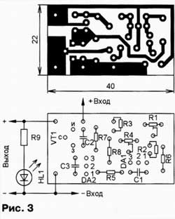
Consider a smooth increase in supply voltage. As long as it is less than 10 V, both microcircuits are closed and the current through the resistor R7 is small. The voltage across this resistor is not enough to open the transistor VT1, the load is off, the HL1 LED is off. When the supply voltage rises to 10 V, the voltage at the control input of the DA2 chip will reach 2,5 V and the chip will open. The current through it will increase, the voltage across the resistor R7 will increase, and the transistor will open and connect the load. Due to the low channel resistance of the open transistor VT1 (0,02 Ohm), the voltage drop across it will be small and almost all of the input voltage is supplied to the load. LED HL1 indicates the on state of the load. When the supply voltage reaches 16 V, the DA 1 chip opens, the voltage on it does not exceed 2 V, as a result of which the DA 2 chip closes, the VT1 transistor also closes and disconnects the load. The HL1 LED will turn off. With a smooth decrease in the supply voltage, the load will be switched on at a voltage of 15 V and switched off at 9 V. Thus, each switching threshold has a hysteresis, which increases the reliability of switching and eliminates multiple switching of the load when an unstable supply voltage fluctuates at the threshold level. The hysteresis of the upper threshold is carried out using positive feedback through the resistor R6, the lower threshold - through the resistor R8. The response thresholds indicated above can be changed over a wide range: the upper one - with a tuning resistor R1, the lower one - R4. Increasing the resistance of resistors R 6 reduces the hysteresis of the upper threshold, R 8 - lower. To reduce the effect of interference, capacitors C1 and C3 are included in the negative feedback circuit of microcircuits, but it should be noted that they reduce the speed of the device. With a load current of 10 A, the voltage drop across the open transistor VT1 will not exceed 0,2 V, and the power dissipation will be no more than 2 W, so the transistor can be used without a heat sink. At 20 A, the power dissipation can reach 8 W, so a small heat sink or two transistors in parallel is required. The supply voltage, taking into account ripples, must be less than the maximum allowable voltage of microcircuits - 30 V. Construction and details Transistor IRF 4905 (VT 1) - field-effect with a p-channel in the TO-220 package or IRF4905L in the TO-262 package, you can also use the IRFU5305 in the TO-251AA package. The KR142EN19 chip (DA1 and DA2) can be replaced by a foreign analogue TL 431 CLR. All capacitors - K10-17 or similar imported, fixed resistors - P1-4, MLT, S2-33, tuning - SPZ-19. For these parts, a board is calculated, the drawing of which is shown in Fig. 3. It is made of one-sided foil fiberglass.
If it is necessary to reduce the overall dimensions of the device, then it is necessary to use surface-mounted parts: transistor VT 1 IRF 4905 S - in the D 2-Pak package or IRFR 5305 - in the D - Pak package, DA1 and DA2 TL431CD microcircuits - in the SOP -8 package, PVZ trimmers, fixed resistors and capacitors - size 1206. A printed circuit board drawing for such parts is shown in fig. 4, photograph of the mounted board - in fig. 5.
LED HL1 can apply any low-power visible radiation spectrum. The resistance of the resistor R 9 is chosen so that at the maximum load supply voltage, the current through the LED does not exceed the maximum allowable value. LED HL1 and resistor R9 are installed outside the board by surface mounting. These elements are only needed if the load does not have its own on indication. Establishment is reduced to setting the switching thresholds by trimming resistors R1 and R4, the required values of hysteresis are set by selecting resistors R6 and R8. Author: I. Nechaev, Kursk; Publication: cxem.net
Machine for thinning flowers in gardens
02.05.2024 Advanced Infrared Microscope
02.05.2024 Air trap for insects
01.05.2024
▪ Smart toilet with electronics and GPS ▪ Electronic tongue recognizes food taste ▪ 24-pin ATX connector will be replaced by 10-pin ▪ Depression and anxiety change brain volume ▪ Poland creates national space agency
▪ section of the site Spy stuff. Article selection ▪ article by Johann Wolfgang von Goethe. Famous aphorisms ▪ article Chistets forest. Legends, cultivation, methods of application
Home page | Library | Articles | Website map | Site Reviews
www.diagram.com.ua |


 Leave your comment on this article: