|
|


 Arabic
 Bengali
 Chinese
 English
 French
 German
 Hebrew
 Hindi
Hindi Italian
 Japanese
 Korean
 Malay
Malay Polish
 Portuguese
 Spanish
 Turkish
 Ukrainian
 Vietnamese
|
ENCYCLOPEDIA OF RADIO ELECTRONICS AND ELECTRICAL ENGINEERING Three phases - no power loss. Encyclopedia of radio electronics and electrical engineering
Encyclopedia of radio electronics and electrical engineering / Electric power supply In various amateur electromechanical machines and devices, three-phase asynchronous motors with a squirrel-cage rotor are most often used. Unfortunately, a three-phase network in everyday life is an extremely rare phenomenon, therefore, amateurs use a phase-shifting capacitor to power them from a conventional electrical network, which does not allow to fully realize the power and starting characteristics of the engine. The existing trinistor "phase-shifting" devices further reduce the power on the motor shaft. A variant of the diagram of a device for starting a three-phase electric motor without power loss is shown in fig. 1.
The windings of the 220/380 V motor are connected in a triangle, and the capacitor C1 is connected, as usual, in parallel with one of them. The capacitor is "helped" by the inductor L1, connected in parallel to another winding. With a certain ratio of the capacitance of the capacitor C1, the inductance of the inductor L1 and the load power, it is possible to obtain a phase shift between the voltages on the three branches of the load, equal to exactly 120 °. On fig. 2 shows a vector voltage diagram for the device shown in fig. 1, with a purely resistive load R in each branch. The linear current ll in vector form is equal to the difference between the currents l3 and I2, and in absolute value it corresponds to the value of If√3, where lf=l1=I2=l3=Un/R - load phase current. Un=U1=U2=U3=220 V - line voltage of the network.
A voltage UC1=U1 is applied to the capacitor C2, the current through it is equal to lc1 and is ahead of the voltage by 90° in phase. Similarly, a voltage UL1=U1 is applied to the inductor L3, the current through it IL1 lags behind the voltage by 90°. If the absolute values of the currents IC1 and IL1 are equal, their vector difference, with the right choice of capacitance and inductance, can be equal to In. The phase shift between the currents IC1 and IL1 is 60°, so the triangle of the vectors Il, lC1 and IL1 is equilateral, and their absolute value is IC1=IL1=Il=If√3 In turn, the phase load current If \u3d P / 1Ul. where P is the total load power. In other words, if the capacitance of the capacitor C1 and the inductance of the inductor L220 are chosen such that when a voltage of 1 V is applied to them, the current through them would be equal to lC1=ILXNUMX=P/(√3Ul)=P/380. shown in fig. 1 circuit L1C1 will provide three-phase voltage to the load with exact observance of the phase shift. In table. 1 shows the values of the current lC1=lL1 of the capacitance of the capacitor C1 and the inductance of the inductor L1 for various values of the total power of a purely active load.
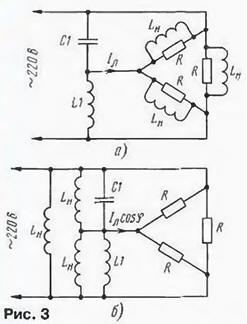
The real load in the form of an electric motor has a significant inductive component. As a result, the linear current lags in phase from the active load current by some angle φ of the order of 20...40°. On the nameplates of electric motors, it is usually not the angle that is indicated, but its cosine - the well-known cosφ, equal to the ratio of the active component of the linear current to its full value. The inductive component of the current flowing through the load of the device shown in fig. 1 can be represented as currents passing through some inductors connected in parallel with the active resistances of the load (Fig. 3, a). or, equivalently, parallel to C1. L1 and network wires.
From fig. 3b it can be seen that since the current through the inductance is antiphase to the current through the capacitance, the inductors Lн reduce the current through the capacitive branch of the phase-shifting circuit and increase it through the inductive one. Therefore, in order to maintain the voltage phase at the output of the phase-shifting circuit, the current through the capacitor C1 must be increased and reduced through the coil. The vector diagram for a load with an inductive component becomes more complicated. Its fragment, which makes it possible to perform the necessary calculations, is shown in Fig. 4.
The total linear current Il is decomposed here into two components: active Ilsosφ and reactive llsinφ. As a result of solving a system of equations to determine the required values of currents through the capacitor C1 and the coil L1 lС1sin30°+ILlsin30°=lсosφ, lС1sin30°-ILsin30°=llsinφ we obtain the following values of these currents: lС1=2/√3 llsin(φ+60°), IL1=2/√3 lcos(φ+30°), With a purely active load (φ=0), the formulas give the previously obtained result: lC1=IL1=Il. On fig. Figure 5 shows the dependences of the ratios of currents lC1 and lL1 to IL on cosφ, calculated using these formulas. For f=30° (cosφ=√3/2\u0,87d 1) the current of the capacitor C2 is maximum and equal to XNUMX / √3Il\u1,15d 1 Il, and the inductor current L0,85 is half as much. The same ratios can be used with a good degree of accuracy for typical cosφ values equal to 0,9 ... XNUMX.
In table. 2 shows the values of the currents IC1, IL1 flowing through the capacitor C1 and the inductor L1 at various values of the total power of the load, which has the above value cosφ=√3/2.
For such a phase-shifting circuit, MBGO capacitors are used. MBGP, MBGT, K42-4 for an operating voltage of at least 600 V or MBGCH. K42-19 for a voltage of at least 250 V. The easiest way to make a choke is from a rod-shaped power transformer from an old tube TV. The no-load current of the primary winding of such a transformer at a voltage of 220 V usually does not exceed 100 mA and has a non-linear dependence on the applied voltage. If, however, a gap of the order of 0.2 ... 1 mm is introduced into the magnetic circuit. the current will increase significantly, and its dependence on voltage will become linear The network windings of transformers TS can be connected as follows. that the nominal voltage on them will be 220 V (jumper between terminals 2 and 2*). 237 V (jumper between pins 2 and 3*) or 254 V (jumper between pins 3 and 3*). Mains voltage is most often applied to terminals 1 and 1 *. Depending on the type of connection, the inductance and current of the winding change. In table. 3 shows the values of the current in the primary winding of the transformer TS-200-2 when a voltage of 220 V is applied to it at various gaps in the magnetic circuit and different switching on of the winding sections.
Comparison of the data in Table. 3 and 2 allows us to conclude that the specified transformer can be installed in a phase-shifting motor circuit with a power of approximately 300 to 800 W and, by selecting the gap and the winding switching circuit, the required current value can be obtained. The inductance also varies depending on the in-phase or anti-phase connection of the network and low-voltage (for example, incandescent) windings of the transformer. The maximum current may slightly exceed the rated current in operation. In this case, to facilitate the thermal regime, it is advisable to remove all secondary windings from the transformer, part of the low-voltage windings can be used to power the automation circuits of the device in which the electric motor operates. In table. 4 shows the nominal values of the currents of the primary windings of transformers of various TVs [1, 2] and the approximate values of the motor power with which it is advisable to use them.
The phase-shifting LC-circuit should be calculated for the maximum possible load of the electric motor. With a smaller load, the necessary phase shift will no longer be maintained, but the starting performance will improve compared to using a single capacitor. Experimental verification was carried out both with a purely active load and with an electric motor. The active load functions were performed by two parallel-connected incandescent lamps with a power of 60 and 75 W, included in each load circuit of the device (see Fig. 1). which corresponded to a total power of 400 watts. In accordance with the table. 1 capacitance of capacitor C1 was 15 uF. The gap in the magnetic circuit of the transformer TS-200-2 (0,5 mm) and the winding connection scheme (at 237 V) were chosen for reasons of providing the required current of 1.05 A. The voltages U1, U2, U3 measured on the load circuits differed from each other by 2 ...3 V., which confirmed the high symmetry of the three-phase voltage. Experiments were also carried out with a three-phase asynchronous motor with a squirrel-cage rotor AOL22-43F with a power of 400 W [3]. He worked with a capacitor C1 with a capacity of 20 microfarads (by the way, the same as when the engine was running with only one phase-shifting capacitor) and with a transformer, the gap and connection of the windings of which were selected from the condition for obtaining a current of 0,7 A. As a result, it was possible to quickly start the engine without a starting capacitor and noticeably increase the torque felt when braking the pulley on the motor shaft. Unfortunately, it is difficult to conduct a more objective check, since in amateur conditions it is almost impossible to provide a normalized mechanical load on the engine. It should be remembered that the phase-shifting circuit is a series oscillatory circuit tuned to a frequency of 50 Hz (for the purely active load option), and this circuit cannot be connected to the network without load. Literature
Author: S. Biryukov, Moscow
A New Way to Control and Manipulate Optical Signals
05.05.2024 Primium Seneca keyboard
05.05.2024 The world's tallest astronomical observatory opened
04.05.2024
▪ The biological clocks of day and night animals differ in their neural structure. ▪ The harm of music before bed ▪ Sony A7R IV Full Frame Mirrorless Camera ▪ DVD+RW discs for video recording
▪ section of the site Electrician in the house. Article selection ▪ article The great writer of the Russian land. Popular expression ▪ article What kind of foreign convicts did they want to populate Russian expanses? Detailed answer ▪ article Ground fault protection. Encyclopedia of radio electronics and electrical engineering
Home page | Library | Articles | Website map | Site Reviews
www.diagram.com.ua |


 Leave your comment on this article: