|
|


 Arabic
 Bengali
 Chinese
 English
 French
 German
 Hebrew
 Hindi
Hindi Italian
 Japanese
 Korean
 Malay
Malay Polish
 Portuguese
 Spanish
 Turkish
 Ukrainian
 Vietnamese
|
ENCYCLOPEDIA OF RADIO ELECTRONICS AND ELECTRICAL ENGINEERING Dumping factor - myths and reality. Encyclopedia of radio electronics and electrical engineering
Encyclopedia of radio electronics and electrical engineering / Transistor power amplifiers Damping factor (in the domestic literature - damping factor) - a characteristic of the amplifier that determines its interaction with the load (acoustic system). In the description of many amplifiers, this parameter takes on an almost mystical meaning. What damping factor is needed and is it worth chasing record numbers? Audio frequency power amplifiers (UMZCH) in relation to the load are divided into two classes - voltage sources and current sources. The latter find very limited use, and almost all serial models are amplifiers - voltage sources. An ideal amplifier, for any load resistance, produces the same voltage at the output. In other words, the output impedance of an ideal voltage source is zero. However, ideal things do not exist in nature, so a real amplifier has a certain internal resistance. This means that the voltage across the load will depend on its resistance (Fig. 1).
However, the loss of output voltage is not the most important consequence of the fact that the amplifier has an output impedance. With any movement of the voice coil in the gap of the magnetic system, an electromotive force (EMF) is induced in it. This EMF, closing through the output resistance of the amplifier, creates a current that opposes the movement of the coil. The magnitude of this current and the braking force are inversely proportional to the output impedance of the amplifier. This phenomenon is called electrical damping of the loudspeaker and largely determines the nature of the reproduction of impulse signals. A dynamic head is a complex oscillatory system that has several resonance frequencies (mechanical resonance of a moving system, internal resonances of a suspension and diffuser, etc.). When a pulsed signal is reproduced, oscillations occur at the resonant frequencies of the system. The trouble is that with weak damping, these damped oscillations can continue even after the impulse that caused them has ended (Fig. 2). As a result, playback will be accompanied by overtones that color the sound.
The task of the audio system designer is to dampen the loudspeaker so that the natural vibrations die out as quickly as possible. However, there are not so many funds for this. There are three ways to dampen the head:
In addition, acoustic damping is included in the design of closed midrange and tweeters. The radiation resistance of the dynamic head also has some effect on acoustic damping. However, the contribution of all these components to the overall degree of head damping is small. Thus, electrical damping becomes the main tool for influencing the transient characteristics of the "amplifier-dynamic head" system. The relationship between the nature of the sound and the output impedance of the amplifier was noticed back in the days of tube amplifiers, in the 50s. Especially noticeable was the difference in the sound of amplifiers with an output stage based on triodes and pentodes. Pentode amplifiers had a significant output impedance, as a result of which the dynamic heads were underdamped and the sound acquired a booming overtone. The introduction of negative feedback made it possible to reduce the output impedance of the amplifier, but did not completely solve the problem. It is surprising that the debate about which amplifier is better continues half a century later. But it's not only the amplifier, but also the speaker system. To evaluate the damping properties of the amplifier, a new parameter was proposed - the damping factor, which is the ratio of the load resistance to the output impedance of the amplifier.
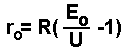
The experiments carried out at the same time made it possible to establish the minimum value of this parameter - 5...8. A further decrease in the output impedance of the amplifier had practically no effect on the impulse response of the system. By the way, the ideology of Hi-Fi (short for High Fidelity - high fidelity) and the term itself took shape by the end of the 50s. At this point, the minimum requirements for the audio system were determined - the band of reproducible frequencies, the harmonic coefficient (then called it clear factor - "degree of purity") and output power. Subsequently, after the advent of transistor amplifiers and specialized low-frequency dynamic heads with a "light" suspension, the lower limit of the damping factor was increased. This made it possible to unambiguously determine the degree of damping of the head by the parameters of the amplifier, regardless of the characteristics of the acoustic design. At the same time, within certain limits, the "sameness" of the sound of a particular speaker with different amplifiers was ensured. The famous DIN45500 standard defined the damping coefficient for Hi-Fi amplifiers unambiguously - at least 20. This means that the output impedance of the amplifier when operating at a load of 4 ohms should be no more than 0,2 ohms. However, the output impedance of modern amplifiers is much less - hundredths and thousandths of an ohm, and the damping factor, respectively, is hundreds and thousands. What is the meaning of such a significant improvement in this indicator? The damping coefficient in this case, oddly enough, has nothing to do with it. Only one of its components is important - the output impedance of the amplifier. In this case, the "magic of numbers" takes place, since everyone is used to hundreds of watts of output power of modern amplifiers and you need to attract the buyer with something new. Agree that "dumping factor 4000" looks much nicer than "0,001 ohm output impedance". And this means in any case only one thing - the amplifier has a very low output impedance and is capable of delivering significant current to the load (even if for a short time). And the connection between the output power and the damping factor, although direct, is not unambiguous. So the term, which used to be of interest only to specialists, found a new application. However, there is one more character in the story of the damping factor - the speaker cable. And he is able to greatly spoil not only the numbers, but also the sound quality. After all, the cable resistance is added to the output impedance of the amplifier and becomes a component of the damping factor. For a cable with a length of 2 m, a resistance of 0,05 ohms is quite a decent indicator. But for an amplifier with an output impedance of 0,01 ohms, the damping factor at a 4 ohm load with such a cable will decrease from 400 to 66. There is no cause for concern yet. But if you use a thin "lace" from a set of speakers and dubious twists with a total resistance of 0,3 ... 0,4 Ohm (the situation, unfortunately, is still not uncommon), then the damping factor will drop to 10, regardless of the amplifier performance. Therefore, it is not worth saving on wires. Passive crossover creates similar problems. Therefore, coils with a ferromagnetic core in crossovers are used more often than "air" ones - this allows not only to save expensive ("they have") copper wire, but also to significantly reduce the resistance of the coil. Of course, when the core is remagnetized, additional non-linear signal distortion occurs, but in most cases this is a lesser evil than underdamped speakers. By the way, the difference in the sound of systems with crossovers of different designs is often determined not so much by the nature of the introduced distortions, but by the different damping of the speaker. In cases where "conscience does not allow" to install coils with a core, the lack of damping can be compensated for by acoustic methods. But acoustic damping does not have all the capabilities of electrical damping and may end up costing more. You can calculate the output impedance of an amplifier in amateur conditions if, with the same input signal, measure its output voltage at idle (Eo) and at a load (U) of a certain resistance (R). However, the accuracy of this simple method degrades when the output impedance of the amplifier is less than 0,05 ohms.
Author: A. Shikhatov; Publication: bluesmobile.com/shikhman
The world's tallest astronomical observatory opened
04.05.2024 Controlling objects using air currents
04.05.2024 Purebred dogs get sick no more often than purebred dogs
03.05.2024
▪ Ground-level ozone reduces tree growth ▪ Purified water can become toxic ▪ Plastic turns into edible mushrooms
▪ section of the site Assembling the Rubik's Cube. Article selection ▪ article Drive beyond Mozhay. Popular expression ▪ Why are pocket knives called penknives? Detailed answer ▪ Article Bacteriologist. Job description
Comments on the article: Vladimir Electrical damping is the ratio of the load resistance to the internal resistance of the amplifier. In this case, it is considered that the larger this ratio is, the faster the natural oscillations of the diffuser decay. In fact, if we take a speaker impedance of 8 ohms and an amplifier resistance of 0,1 ohms or 1 ohm, then the damping will have values of 80 units or 8 units. Anyone will tell you that 80 is much larger than 8, and damped 80 cone eigenmodes will decay much faster. But no. The EMF of the speaker coil during its own oscillations is loaded on a circuit of two resistances - the speaker itself and the output resistance of the amplifier. It turns out the load of the EMF speaker at 8.1 ohms or 9 ohms. The difference is only 10% and not 10 times. Now, if the output impedance of the amplifier is 8 ohms, then the natural oscillations of the diffuser will be 2 times longer than with an amplifier resistance of 0.1 ohms or even 1 ohm. Therefore, I consider the concept of the dumping factor to be far-fetched in order to fool the brains of ignoramuses. If we take a tube amplifier, which, according to many reviews, has a better sound, then, theoretically, with optimal transformer matching of the speaker impedance to the output tube, the output impedance will be equal to the speaker impedance. The damping factor is 1!!!!!! Oleg This article is outdated and does not meet modern requirements. The theory in this case is far from practice. To begin with, comparative listening of an amplifier with a CD-thousand or more, compared to an amplifier with a small CD - shows a significant difference in sound. This is easily verified and does not correspond to the theory, because, in theory, they forgot that the CD value is frequency-dependent and is normalized at a frequency of 1 kHz. And at 20 Hz -? That's why the amplifier needs to be normalized at low frequencies, and not where it works best. And, the next question is the resistance of the amplifier itself to back EMF. Ie - the amplifier must be checked for external influence on its output. This technique was proposed by S. Ageev. And, it is quite obvious that there are no clear criteria, measurement methods and measured values by which it is possible to assess whether the amplifier really dampens the speaker and how it reacts to back EMF and load non-linearity. Hence the conclusion that more than a thousand CD is definitely better than 100, although in theory this is enough ...
Home page | Library | Articles | Website map | Site Reviews
www.diagram.com.ua |


 Leave your comment on this article: