|
|


 Arabic
 Bengali
 Chinese
 English
 French
 German
 Hebrew
 Hindi
Hindi Italian
 Japanese
 Korean
 Malay
Malay Polish
 Portuguese
 Spanish
 Turkish
 Ukrainian
 Vietnamese
|
ENCYCLOPEDIA OF RADIO ELECTRONICS AND ELECTRICAL ENGINEERING The digital multimeter measures temperature. Encyclopedia of radio electronics and electrical engineering
Encyclopedia of radio electronics and electrical engineering / Power regulators, thermometers, heat stabilizers Using a specialized K1019EM1 chip, a digital multimeter can be turned into a temperature meter with increased accuracy. Digital multimeters DT830B with a display capacity of 3,5 can be easily supplemented with a K1019EM1 thermal sensor chip. However, the output signal of this microcircuit in the operating temperature range is in the range of 2331 ... 3931 mV and it can be measured only at the limit of the voltmeter 20 V, and the temperature value displayed on the display will be in °K. The device described in the published article is designed to reduce the output voltage of the K1019EM1 chip by 2731,5 mV. The output voltage converted in this way will correspond to the temperature in the usual °C. Integrated circuits K1019EI1 and K1019EM1A [1, 2] are sensitive thermal sensors with a linear dependence of the output voltage on the absolute temperature: Uout=at.Tk, where at=10 mV/K is the voltage temperature coefficient, Tk is the absolute temperature in degrees K. The accuracy parameters of these microcircuits are quite high - the error of the output voltage of a microcircuit calibrated at a temperature of +25°С does not exceed 45 mV within the entire operating temperature range of 125 ... +10°С, i.e., it is less than 1°С, and in the range 0...+40°С - 0,1°С. In the described device, the internal source of the ADC of the multimeter itself is used as a reference voltage source. When the temperature sensor connector is disconnected, the current consumed by the device does not exceed 100 μA, and when the sensor is connected, it increases by the operating current of the K1019EM1 chip, which is approximately 1 mA. A schematic diagram of a device for measuring temperature working with a multimeter (voltmeter) is shown in fig. 1. It consists of an additional board A1.1 and a thermal converter A2. On the additional board, a DC bias assembly is mounted, assembled on an operational amplifier DA1 and a transistor VT1. The magnitude of the voltage offset on the collector of the transistor VT1 relative to the output 32 of the ADC is 2731,5 mV. Trimmer resistor R1 serves to fine-tune this value. Capacitor C1 corrects the frequency response of the section of the voltage bias node covered by negative feedback through resistor R5, which eliminates self-excitation. Transistor VT2 and resistors R11-R13 form a stable current generator of about 1 mA. The thermal converter consists of a K1019EM1 thermal sensor microcircuit, R8-R10 resistors and a X1 connector plug. Resistor R9 corrects the output voltage of the microcircuit.
The additional board for the temperature measurement device with a DT830B multimeter is made of a single-sided fiberglass plate with dimensions of 32x32 mm. The location of the elements on this board is shown in fig. 2.
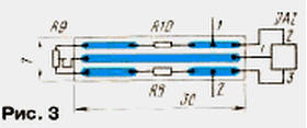
After installing all the mounting elements on the board and soldering the external conductors to the pads with side cutters, their ends protruding from the side of the printed conductors to 1,5 ... 2 mm are shortened, otherwise the board will not fit in the multimeter case in height. After that, with the help of bars made from matches, the additional board is glued with Moment glue to the free area of the multimeter printed circuit board. The thermal converter is also mounted on a fiberglass printed circuit board. Placement of the elements of the thermal converter on it is shown in fig. 3.
Open contact pads and resistors of the thermal converter should be covered with varnish or BF-2 glue. The thermal converter assembly can be connected to the multimeter unit with any two-wire cable of the desired length. The author, for example, used a telephone cable with a length of about 8 m. The functions of the detachable connector are performed by a three-pole switching plug from stereo headphones with a nominal diameter of 3,5 mm and a three-pole switching socket 1308 IEC-pp. On fig. 4 is a sketch of a three-pole plug and socket. The latter is installed in a hole specially drilled for it on the side of the multimeter case. The plastic base of the socket should fit snugly against the plane of the multimeter case. For strength, the joints are coated with glue, which is used in the manufacture of plastic models. A conductor connecting 1 and 3 of its conclusions is soldered to the switching plug. This conductor connects the multimeter's test input to the sensor only during temperature measurements.
The temperature meter uses tuning resistors SPZ-19a (R1, R9), constant C2-29V (R2, R3, R5, R8, R9) and OMLT (others). Capacitor C1 is ceramic of any type. The device is configured in the following order. First, a temperature sensor is connected to connector X1 and the voltage between the collectors of transistors VT1 and VT1 is set by resistor R2 to 2731,5 mV. After that, the temperature-sensitive transducer, together with a medical thermometer, is placed under the arm, and after 5 minutes, the thermometer readings are compared with the readings on the digital display of the multimeter, which is switched on in the voltmeter mode to the limit of 2000 mV. If these readings do not match, you need to adjust the multimeter using resistor R9. Then the temperature should be measured again and, if necessary, a correction is made again. When the same readings of the medical thermometer and multimeter are reached, the setting is completed. In conclusion, it should be noted that the described device can be used in conjunction with any digital voltmeter based on the ADC K572PV2, K572PV5, K572PV6. A possible area of its application is remote temperature measurement inside and outside residential and utility rooms, vegetable and granaries, and other facilities that require temperature control. Literature
Author: V.Porotnikov, Yekaterinburg
Machine for thinning flowers in gardens
02.05.2024 Advanced Infrared Microscope
02.05.2024 Air trap for insects
01.05.2024
▪ Aqua Computer Kryographics Next full coverage water blocks ▪ Transmission of odors over a distance ▪ Image Sensor ON Semiconductor AR0221 ▪ The resolution of smartphone screens has reached the capabilities of human vision ▪ High-speed network will unite scientists from China, Russia and the USA
▪ site section Parameters of radio components. Article selection ▪ article Correspondence of models and chassis DVD GRUNDIG. Directory ▪ article Which gesture we are accustomed to is also a symbol of San Francisco's gays? Detailed answer ▪ article Sweet root. Legends, cultivation, methods of application ▪ article Side mirror drive repair. Encyclopedia of radio electronics and electrical engineering
Home page | Library | Articles | Website map | Site Reviews
www.diagram.com.ua |


 Leave your comment on this article: