|
|


 Arabic
 Bengali
 Chinese
 English
 French
 German
 Hebrew
 Hindi
Hindi Italian
 Japanese
 Korean
 Malay
Malay Polish
 Portuguese
 Spanish
 Turkish
 Ukrainian
 Vietnamese
|
ENCYCLOPEDIA OF RADIO ELECTRONICS AND ELECTRICAL ENGINEERING Security alarm radio channel based on the URAL radio station. Encyclopedia of radio electronics and electrical engineering
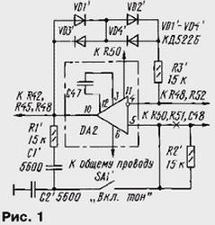
Encyclopedia of radio electronics and electrical engineering / Safety and security Single-channel CB radio stations (such as, for example, "Ural") are already obsolete, but meanwhile they can still serve their owners. A small refinement will allow them to give a second life, after which they can be used in the radio channel of security systems. When guarding a garage or a car, using a radio channel, an alarm signal can be transmitted over a considerable distance. To create such a security system, two Ural radio stations will be needed, which will require a little refinement: one of them is installed at a protected facility, and the other at home. Let's start with finalizing the station at a protected facility. First, it must be equipped with a tone generator. This is necessary so that the alarm signal is distinguishable against the background of noise or interference, in addition, the generator can also be used for tone selective calling. The refinement scheme is shown in fig. 1 (the designation and location of parts is given in accordance with the diagram of the radio station given in the operation manual). All newly introduced details are marked with a dash.
The positive feedback circuit of the AF amplifier on the op amp DA2 includes an RC circuit R1'C1'C2'R2' with a toggle switch SA1', which is a Wien bridge. When the toggle switch is closed, generation occurs at a frequency of approximately 1,4 kHz. Diodes VD1'-VD4'resistor R3' are included in the negative feedback circuit. This circuit provides stabilization of the amplitude of the generated oscillations, and in the radio mode (when SA1' is open), it also provides signal compression, which limits the radiated frequency band. The PCB track coming from pin 5 of the DA2' chip is cut and resistor R2' is soldered to it. Toggle switch SA1' (any small) is installed on the side or front wall of the housing. The remaining parts can be placed on a small printed circuit board, which is glued directly to the DA2 chip body. In addition, to increase the stability of operation, it is desirable to replace the capacitor C47 with another one with a capacity 2 ... 3 times larger. And frequency stability will be provided by capacitors with TKE no worse than the M750. If you install a small-sized button on the receive / transmit key and turn it on in parallel with SA1 ', then this button can generate the "end of transmission" signal or give tone signals. The next problem to be solved is the provision of the transfer mode. The fact is that the switching of reception / transmission modes is carried out using a mechanical switch, driven by a special key. To transmit an alarm, the transmitter must be turned on, and for this, in turn, a key must be pressed. In the key, in the place where, when pressed, it presses on the switch, you need to drill a hole with a diameter of 3 ... 4 mm and melt an M3 or M4 nut into it. In this case, to put the radio into a long-term alarm transmission mode, you must set SA1 to the closed state and screw the screw into the nut until it stops so that the mechanical receive / transmit switch switches to the "Transmit" position. If you now apply power to the radio station, then it will begin to broadcast an alarm tone, and this will be the watchdog device, which will be discussed below. To protect the premises and turn on the transmitter, you need the watchdog itself, its diagram is shown in fig. 2. The room is controlled by wire loops and sensors (SF1). When the device is turned on, a high level occurs at the input of the logic element DD1.1, while its output will be low, and the output of DD1.2 will be high. The output of the element DD1.4 will be low, therefore, the output of DD2.1 will be high. This signal disables the operation of the pulse generator, assembled on the elements DD2.2, DD2.3. The output of DD2.4 is low, the transistor VT1 will close, and the radio station is de-energized. The position of the SF1 sensor (there may be several connected in series) at this time will not affect the operation of the device.
This will continue until the capacitor C1 is charged, which will take several tens of seconds. This time is necessary in order to close the protected premises or object. After that, the device will begin to respond to the state of the SF1 sensor. If the contacts are open (even briefly), then a high level through resistor R2 will go to input 13 of element DD1.3. The RS-trigger on the elements DD1.3 and DD1.4 will change its state - a high level will appear at the output of DD1.4 and the capacitor C4 will start charging. Now, no manipulations with the sensor will change the state of the trigger, but until the capacitor C4 is charged, the generator will not work and the transistor VT1 will remain closed - the alarm will not go on air. This period of time will last several tens of seconds, necessary in order to have time to turn off the security device. If during this time the device is not turned off, then the generator on the elements DD2.2 and DD2.3 will start working. This means that the transistor VT1 will open and turn on the transmitter for about 1 ... 2 s. With the same pause, an alarm signal will go on the air. The watchdog does not require adjustment. The required turn-on and turn-off delay time can be selected with resistors R1 and R3 or capacitors C1 and C4. It is better to power the watchdog from an independent source, for example, an old car battery. Even in poor condition, it is suitable for this purpose. As opening contacts, it is convenient to use reed switches that work in tandem with a magnet. You can, of course, receive an alarm signal to any radio station or a simple single-channel home-made radio receiver. However, it is more reliable to use, as already noted, the second copy of the Ural radio station installed at home. It hardly needs to be said that it is inconvenient to keep the radio station on all the time, and even at high volume. The fact is that it does not have a noise suppressor, and constantly listening to noises or colloquial speech (after all, a public channel) is not a very pleasant pleasure. The way out can be to install a special selective device in the radio station to highlight only "its" alarm signal, and at the same time, a good noise suppressor. A diagram of such a device is shown in Fig. 3. It consists of two active band-pass filters (one - on the DA1.1 op-amp with a center frequency of about 7 kHz, the second - on the DA1.3 with a center frequency of 1,4 kHz), an AC voltage amplifier with adjustable gain on the DA1.2 op-amp. 1, two diode detectors (VD2VD3 and VD4VD1.4), a comparator on DA1 and a key on the transistor VT174. The device is connected between the output of the FM detector (IC K3UR38) and the volume control R174. The detected signal from the AF output of the K3UR1.1 microcircuit is fed to the inputs of active filters (DA1.3, DA1) and to the VTXNUMX key.
In the squelch mode (toggle switch SA1 is closed) at the inverting input of the comparator DA1.4 there is a constant voltage close to the voltage of the power supply. The filtered and amplified noise signal through resistor R10 and capacitor C8 is fed to the detector VD1VD2 and then to the non-inverting input of the comparator. If no signal is received at the receiver, then the noise level at frequencies of about 7 kHz will be maximum, the voltage at the non-inverting input of the DA1.4 comparator will exceed the voltage at the inverting input, so the DA1.4 output will have a voltage close to the supply voltage. In this case, the field effect transistor VT1 is closed and the noise does not pass to the volume control. Upon receipt of a speech or tone signal, the noise level at frequencies of about 7 kHz will decrease and the voltage at the output of the VD1VD2 detector will decrease, the comparator DA1.4 will switch, the transistor VT1 will open and the useful signal will pass to the volume control. The noise suppressor threshold is set by a variable resistor R6. This mode is convenient to use when making connections. In the selective call (CB) mode, the SA1 toggle switch is open and the voltage at the inverting input of the comparator DA1.4 is determined by the voltage at the output of the VD3VD4 detector. In the absence of speech or tone signals, the voltage at the output of the DA1.2 amplifier is greater than at the output of the DA1.3 filter (1,4 kHz), therefore, the voltage at the output of the comparator is about 5 V and the transistor VT1 is closed - noise does not pass to the volume control. When the receiver receives a speech signal, the voltage at the input of the DA1.2 amplifier will decrease, so the voltage at the output of the VD1VD2 detector will drop to about 1 V (it is determined by the resistive divider R17R13). The voltage at the output of the VD3VD4 detector will not be enough to switch the comparator and the transistor will remain closed. When a periodic alarm with a frequency of 1,4 kHz is received, the voltage at the output of the active filter DA1.3 will increase. Consequently, the voltage will also increase at the output of the VD3VD4 detector. The comparator will switch, the voltage at its output will decrease and the transistor VT1 will open - an alarm signal will go to the input of the ultrasonic frequency converter. The sensitivity of the device in this mode can be adjusted by the trimming resistor R9. All parts, except for the variable resistor R6 and the SA1 toggle switch, are placed on the printed circuit board, which is installed in the radio station housing, next to the dynamic head. It is desirable to use capacitors C3, C4, C6, C7 with TKE not worse than M750. Connections to the FM output of the detector and the volume control are best made with thin shielded wire. Establishment begins with checking the noise suppressor, with proper installation, it usually starts working immediately. Then, the sensitivity of the device is adjusted in the selective call mode with resistor R9, for this, the signal of the first radio station is used. The position of the slider of the resistor R9 must be chosen so that the device does not work when receiving a speech signal and works stably when receiving a tone signal from the first radio station. Author: I. Nechaev, Kursk
Machine for thinning flowers in gardens
02.05.2024 Advanced Infrared Microscope
02.05.2024 Air trap for insects
01.05.2024
▪ 200MP Samsung ISOCELL HP3 sensor ▪ Fairy robot for plant pollination ▪ L-band antenna supporting ultra-wideband and multi-band networks ▪ Kite received a bionic prosthetic leg
▪ section of the site Signal limiters, compressors. Article selection ▪ article by Han Fei. Famous aphorisms ▪ article Which gnomes often travel the world without the knowledge of their masters? Detailed answer ▪ Arrowhead article. Legends, cultivation, methods of application
Home page | Library | Articles | Website map | Site Reviews
www.diagram.com.ua |


 Leave your comment on this article: