|
|


 Arabic
 Bengali
 Chinese
 English
 French
 German
 Hebrew
 Hindi
Hindi Italian
 Japanese
 Korean
 Malay
Malay Polish
 Portuguese
 Spanish
 Turkish
 Ukrainian
 Vietnamese
|
ENCYCLOPEDIA OF RADIO ELECTRONICS AND ELECTRICAL ENGINEERING Echo sounder. Encyclopedia of radio electronics and electrical engineering
Encyclopedia of radio electronics and electrical engineering / Home, household, hobby The echo sounder offered to the attention of readers can be used to determine the bottom topography and measure the depth of water bodies, search for sunken objects, and also find the most promising places for fishing. The device is very easy to set up, easy to use and does not require calibration. The echo sounder is designed to measure the depth of water bodies within four limits: up to 2,5; 5; 12,5 and 25 m. The minimum measured depth is 0,3 m. The indication error does not exceed 4% of the upper value at any measurement limit. The device has a temporary automatic gain control (TAG), which allows you to change its gain during each measurement cycle from minimum to maximum and, thus, increasing noise immunity. The need for TVG is due to the fact that any radiation of acoustic energy into water leads to intense reverberation, i.e., multiple reflections of an ultrasonic signal from the bottom and surface of the water. Therefore, at shallow depths, there may be false alarms of the echo signal registration unit. Thanks to VAR, the operation of the device is significantly improved when measuring depth in the range of 0,3 ... 3 m. The echo sounder uses a linear depth scale consisting of 26 LEDs as an indicator, which can display up to four reflected measurement limits. The update period of information on the indicator is about 0,1 s, which makes it easy to track the bottom topography while moving. Additionally, the echo sounder's noise immunity is increased by a software impulse filter that protects it from random noise. When the filter is enabled, only those reflected signals are displayed on the indicator, the values of which during the measurement period (0,1 s) have changed by no more than 1/50 of the enabled measurement limit. The device is powered by six A316 elements, and its performance is maintained when the voltage drops to 6 V. The consumed current lies in the range of 7 ... 8 mA (without taking into account the current through the LEDs - 10 mA for each lit LED). The echo sounder provides for the possibility of prompt switching of the measurement limit, the number of reflected reflections, as well as adjustment of the TVG efficiency. The impulse filter can be disabled if necessary. The values of all parameters can be stored in the memory in a low power mode ("SLEEP"). In this mode, the current consumed by the device is about 70 μA, which practically does not affect the battery life. The echo sounder consists of four functionally complete units: a probing pulse generator, a receiver, a control unit, and an indication unit (Fig. 1).
Schematic diagram of the probing pulse generator is shown in fig. 2.
The master pulse generator is assembled on a DD1 chip. It generates pulses with a frequency of 600 kHz, which is then divided into two by a trigger on the DD2 chip. A buffer stage is assembled on the DD3 microcircuit, matching the trigger with a power amplifier made according to a push-pull circuit on composite transistors VT1, VT2 and transformer T1. From its secondary winding, electrical oscillations with a frequency of 300 kHz are fed to a piezoceramic emitter - sensor BQ1 and are emitted into the external environment in the form of ultrasonic packages. The operation of the generator is allowed if there is a logic zero level at pins 12, 13 of the DD1 chip and 4, 6 of the DD2 chip. An enabling pulse with a duration of 50 µs arrives at the generator at the beginning of each measurement cycle from the control device (Fig. 3). All signals necessary for the operation of the device form a single-chip microcontroller DD1 (AT89S2051). The machine codes of the control program located in the internal program memory of the microcontroller are shown in the table.
The checksums were calculated using the "Radio-86RK" algorithm. Transistors VT1-VT4 are equipped with a voltage stabilizer of 5 V. Its characteristic features are a small current consumption - 25 μA and a small voltage drop across the control transistor - less than 1 V. The VT5 transistor turns off power from the receiver in the "SLEEP" mode, which, as indicated higher, reduces the current consumption.
The pulse signal reflected from the bottom is received in the interval between transmissions by the emitter-sensor and fed to the input of the receiver (Fig. 4), where it is amplified by a three-stage resonant amplifier based on transistors VT1, VT2, VT4-VT7, after which it is detected by diodes VD4, VD5. The Schmitt trigger on transistors VT8, VT9 generates standard logic levels. Diodes VD1, VD2 protect the receiver input from overload. Transistor VT3 performs the functions of a control element VAG, which changes the gain of the cascade on transistors VT1, VT2 over a wide range.
The shape of the control voltage on the capacitor C1 at the maximum efficiency of the TVG is shown in fig. 5.
The duration of the capacitor charging is determined by the time constant of the R2C1 circuit, and the lower voltage level is determined by the resistance of the resistor R4 and the duration of the discharge pulse from the control device, which can vary from 0 to 1,25 ms. Accordingly, the efficiency of the TVG also changes, which allows you to quickly adjust the sensitivity of the echo sounder for specific operating conditions. From the collector VT9, the generated reflected pulse is fed to the output P3.2 of the microcontroller DD1 of the control device for further processing. The diagram of the display unit is shown in fig. 6. It is a 32-bit shift register on four microcircuits DD1-DD4 (K561IR2) with emitter followers at the output.
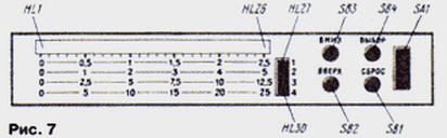
Resistors R1-R30 set a current of 10 mA through the LEDs HL1-HL30. With this current, the indicator is clearly visible in any weather. The last two bits of the DD4 chip are not used. LEDs HL1-HL26 form the main scale of the indicator, and HL27-HL30 indicate the measurement limit, the number of displayed reflections and the inclusion of a pulse noise filter. Their placement on the front panel is shown in Fig. 7.
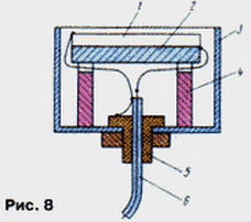
Buttons SB1-SB4 (see Fig. 1) are also displayed on the front panel; with their help, they quickly change the operating modes of the echo sounder. The design of the ultrasonic emitter-sensor is illustrated in Fig. 8. It is a round plate 1 with a diameter of 31 mm and a thickness of 6 mm made of piezoceramic TsTS-19 with a resonant frequency of 300 kHz. Three pieces of MGTF-0,1 wire are soldered to the silver-plated planes of the plate with Wood's alloy. Solder points should be located at the edge of the plate and evenly spaced around its circumference.
The sensor is assembled in an aluminum cup 3 from an oxide capacitor with a diameter of about 40 and a length of 30...40 mm. In the center of the bottom of the glass, a hole is drilled for fitting 5, through which a flexible coaxial cable 6 1 ... 2,5 m long enters, connecting the sensor with the echo sounder. The sensor plate is glued to a disk of soft microporous rubber 2 with a thickness of 5...10 mm and a diameter equal to the diameter of the plate. The conclusions soldered to the piezoelectric element are assembled into a bundle so that its axis coincides with the axis of the piezoelectric element. During installation, the cable braid is soldered to the fitting, the central conductor - to the terminals of the sensor lining glued to the rubber disk, the leads of the other lining - to the cable braid. Technological racks 4 fix the position of the plate so that its surface is deepened into the glass 2 mm below its edge. The glass is fixed strictly vertically and poured to the edge with epoxy. In this case, you need to make sure that there are no air bubbles in it. The echo sounder uses commonly used parts. Coil L1 of the generator is wound on a frame with a diameter of 5 mm with a trimmer 1000НН. It contains 110 turns of PEV 0,12 wire. Transformer T1 is made on an annular magnetic circuit K16x8x6 mm from M1000NM ferrite. The primary winding is wound in two wires and contains 2x20, the secondary - 150 turns of PEV 0,21 wire. A layer of varnished cloth is laid between the windings. The receiver coils are wound on frames from the IF circuits (465 kHz) of pocket receivers. The loop coils L1, L3, L5 each contain 90, and the communication coils L2 and L4 each contain 10 turns of PEV wire 0,12. You can also use ready-made IF circuits from pocket receivers of the 70s and 80s, choosing capacitors to obtain a resonant frequency of 300 kHz. Capacitors C1, C2 of the generator and C5, C9, C13 of the receiver must have a small TKE (not worse than M75), for example, capacitors KSO-G, KM-5, KM-6 are suitable. Capacitor C1 of the receiver - K73-17. Indicator LEDs HL1-HL30 of a red glow of a rectangular shape, for example KIPM01B-1K. Field-effect transistors VT2, VT4 of the stabilizer (see Fig. 3) - KP303, KP307 with any letter index, but with a cut-off voltage of not more than 2 V. The AT89C2051 microcontroller can be replaced with AT89C51 or 87C51. In this case, it is necessary to take into account the differences in the numbering of conclusions. The domestic analogue of 87C51 is KR1830BE751. The use of the KR1830BE31 microcontroller with external program memory is impractical, since this will significantly increase the current consumption and the dimensions of the device. You can get acquainted with the internal structure and command system of the microcontroller in detail in [1]. There are no special requirements for the rest of the details. All sonar units can be mounted on one or more printed circuit boards, the dimensions and configuration of which are determined by the dimensions of the housing available, as well as the parts used. It is desirable to mount the receiver on a separate board "in a line" and place it in the case as far as possible from the control device. To reduce heating from direct sunlight, the case should be light. The establishment of the echo sounder begins with the installation of +5 V at the output of the stabilizer of the voltage control device. This is done using the resistor R5. In this case, the DD1 chip should be removed from the socket. After installing the microcontroller in place, it is necessary to make sure that the control device and the display unit are operational. After the power is turned on, one of the LEDs of the additional scale (HL27-HL30) should light up on the indicator, indicating the measurement limit. By pressing the buttons SB2 "Up" and SB3 "Down", you can switch the measurement limits. A single press of the SB4 "Select" button switches the device to the mode of setting the number of reflected reflections. Similarly, by pressing the buttons SB2 and SB3, you can change this number from 1 to 4, which is indicated by a flashing LED on the limit scale. The next time you press the SB4 button, the mode of setting the degree of VAGC is activated, which is also regulated by the SB2 or SB3 buttons and is indicated by a flashing LED on the main depth scale. By pressing the SB4 button again, you can also turn off or turn on the pulse noise filter using the SB2 and SB3 buttons, respectively. Finally, the fourth press of the SB4 button returns the device to the main mode of switching limits. In all modes, reflected pulses (if any) will be displayed on the depth indicator, and if the depth is greater than the set limit, the last depth indicator LED - HL26 - will flash in the main mode. To memorize the selected modes, press and hold the SB4 button for about 2 s. After that, the indicator goes out and the device enters the "SLEEP" low power mode. Exit from this mode occurs when you press the button SB1 "Reset". However, if you press SB1 in the operating mode, all parameters will be reset to the original state recorded in the ROM. After making sure that the microcontroller is working properly, they proceed to setting up the probing pulse generator. First, you need to use an oscilloscope to make sure that there is a negative pulse with a duration of 50 μs with a period of 100 ms at the P1.0 pin of the microcontroller. Then the oscilloscope is connected in parallel to the emitter-sensor and the generated probing pulses are observed. Their amplitude can reach 100 V. By lowering the emitter into a vessel with water at least 40 cm deep, one can also observe the reflected pulses. By rotating the coil trimmer L1, you should tune the generator to the resonant frequency of the emitter, focusing on the maximum amplitude of the reflected pulses. The amplitude of the first of them can reach 5...10 V. The amplitude of the probing pulse is practically independent of the frequency. Establishing the receiver begins with setting the transistor modes for direct current in accordance with those indicated on the circuit diagram. This operation should be carried out with the microcontroller removed from the socket. If necessary, the modes can be adjusted with divider resistors in the base transistor circuit. Then you need to tune the resonant circuits to the frequency of the generator. To do this, the emitter located in the air is placed at a distance of 15 ... 20 cm from any obstacle and, using an oscilloscope, the circuits are adjusted according to the maximum amplitude of the pulses on the collectors VT1, VT4, VT6. In this case, it must be taken into account that the radiation pattern of the emitter in air is very narrow. As you tune, you should increase the effectiveness of the TVG or increase the distance to the obstacle to avoid signal clipping. Finally, the contours are adjusted by observing the signal after the detector at the junction of the elements R21, C17, C18. Finally, by connecting the oscilloscope to the collector of the VT9 transistor, the trimmer resistor R22 sets the Schmitt trigger threshold, achieving maximum sensitivity and the absence of false positives. The sensitivity of the receiver is about 15 μV. The work of the TVG is controlled by observing the voltage waveform on the capacitor C1 of the receiver. If necessary, it can be changed by selecting the values of the elements R4 and C1. The theory and practice of measuring the depth of water bodies with an ultrasonic echo sounder can be found in the literature below [2-7]. Literature
Author: I. Khlyupin, Dolgoprudny, Moscow Region
Machine for thinning flowers in gardens
02.05.2024 Advanced Infrared Microscope
02.05.2024 Air trap for insects
01.05.2024
▪ Hydrogen crossover Audi H-Tron Quattro ▪ Created the most powerful magnet in the world
▪ site section Measuring equipment. Article selection ▪ article Smooth seams - a teaspoon. Tips for the home master ▪ article Which parasitic tree can cut underground telephone cables? Detailed answer ▪ article Consultant on taxes and fees. Job description ▪ article Electric spoon. physical experiment
Home page | Library | Articles | Website map | Site Reviews
www.diagram.com.ua |


 Leave your comment on this article: