|
|


 Arabic
 Bengali
 Chinese
 English
 French
 German
 Hebrew
 Hindi
Hindi Italian
 Japanese
 Korean
 Malay
Malay Polish
 Portuguese
 Spanish
 Turkish
 Ukrainian
 Vietnamese
|
ENCYCLOPEDIA OF RADIO ELECTRONICS AND ELECTRICAL ENGINEERING Clock for automatic device management. Encyclopedia of radio electronics and electrical engineering
Encyclopedia of radio electronics and electrical engineering / Clocks, timers, relays, load switches To automatically control the operation of various household electrical appliances or radio equipment at home, as well as in production, it is sometimes necessary to have a time setting machine. For example, such a device can, according to a given program, control the watering of plants in a summer cottage throughout the week while you work in the city. The cyclic timer is easy to implement based on a digital clock with quartz frequency stabilization. It is inconvenient to use ready-made industrial-made digital clocks for the manufacture of a control machine, since their output signals are designed to control indicators in a dynamic mode, which makes it difficult to connect the control unit. Most often, in published designs for the manufacture of electronic clocks, the 70th series of MOS microcircuits, specially developed for these purposes back in the 176s, is used. Currently, they are outdated and have significant drawbacks:
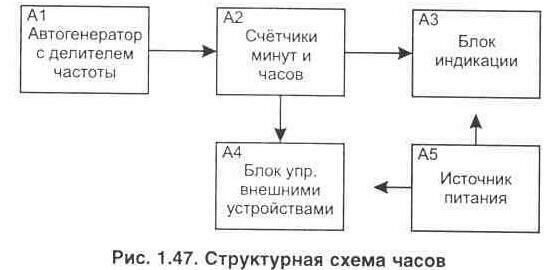
The proposed device is made mainly on microcircuits of the 561st CMOS series and is devoid of all these shortcomings. Although this circuit contains more microcircuits and is more complex, but it works with a lower supply voltage, and also allows you to achieve higher clock accuracy. The electrical circuit provides an indication of the current time (hours and minutes) and the day of the week. There is an indication of second pulses, and it is also possible to control the operation of the program (daily cycle) in an accelerated mode. The main power source of the device is 220 V. In standby mode, the clock circuit consumes microcurrent, which ensures its long-term operation from backup batteries (battery) in case the main source is turned off. Considering that LED indicators and the microcircuits that control them consume the most energy in watches, these elements are connected in such a way that in the event of a power failure they are de-energized, and only the CMOS microcircuits are powered from the battery. The use of LED indicators in the clock allows you to make the time visible even in low light. The above version of the device allows you to control the network load up to 10 kW (current 5 A) via two channels. The number of channels is easily increased to 10 by connecting additional memory chips. In addition, during installation, the circuit can easily be changed in its characteristics depending on the tasks that need to be performed, for example, all channels or one of them can work in a weekly cycle (for weekends, write your own control program if two high-order inputs A11 and A12 memory chips connected to the outputs of the weekday counter - DD9). The resolution of setting the required time interval is 2 minutes (or 10 minutes when using a weekly cycle). The block diagram of the automaton is shown in fig. 1.47.
For ease of presentation, the device is conditionally divided into the following nodes:
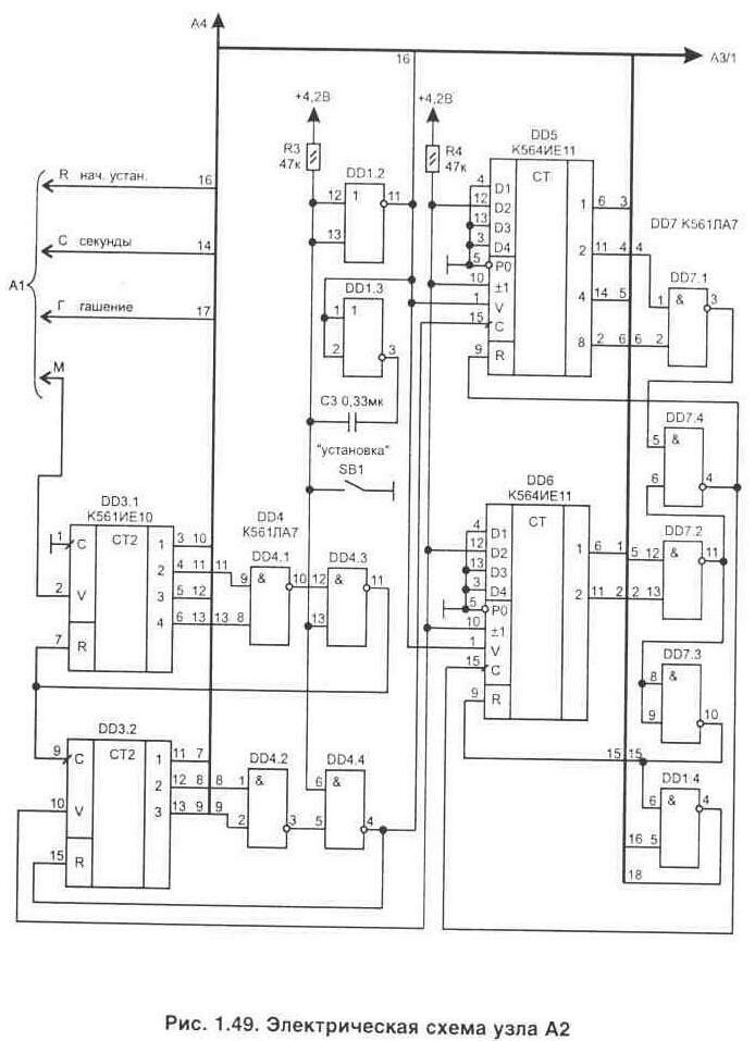
The minute pulse shaper (A1) is made on microcircuits DD1.1, DD2. The frequency is stabilized by a ZQ1 quartz resonator at 32768 Hz. In order to ensure stable operation of the counter DD2 at low supply voltage, the master oscillator is made on an external element DD1.1. The counters inside the DD2 chip divide the frequency until the formation of minute pulses. From the output DD2 / 10, minute pulses are fed to counters with a division factor of 60 (minutes) DD3 and 24 (hours) DD5, DD6 (Fig. 1.49).
Logical elements DD4 and DD7 provide the necessary division ratios for the counters by resetting them to zero at the right time via the inputs R. Pressing the "set" button (SB1) also generates a reset pulse for all counters, and from the output of element DD1 / 11, the leading edge of the pulse sets to the counters DD5, DD6 initial number 22-00 (when a pulse appears at the outputs DD5/1, DD6/1, the binary code set at the inputs D1 ... D4 of the microcircuits is recorded). The time for the initial setup during the manufacture of the device can be selected (by jumpers in binary code) by any of those numbers that are most convenient for you. The use of just one button to set the time allows you to simplify the scheme. The same button, when pressed again, switches the day of the week, since the pulses come through the element DD1.4 to the input of the day counter DD9 / 14, fig. 1.50. Capacitor C eliminates the bounce of the button contacts when an impulse is generated to switch the counter of the day of the week.
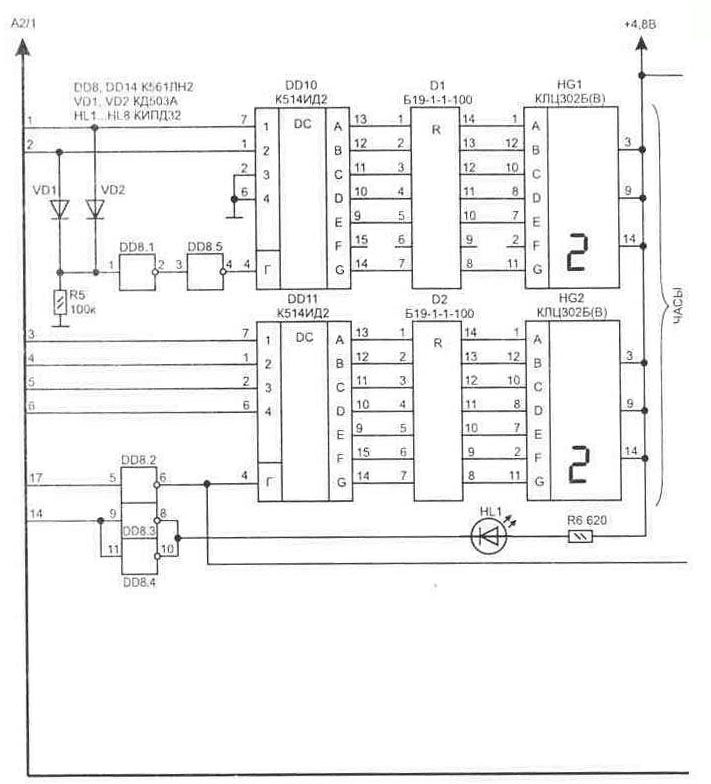
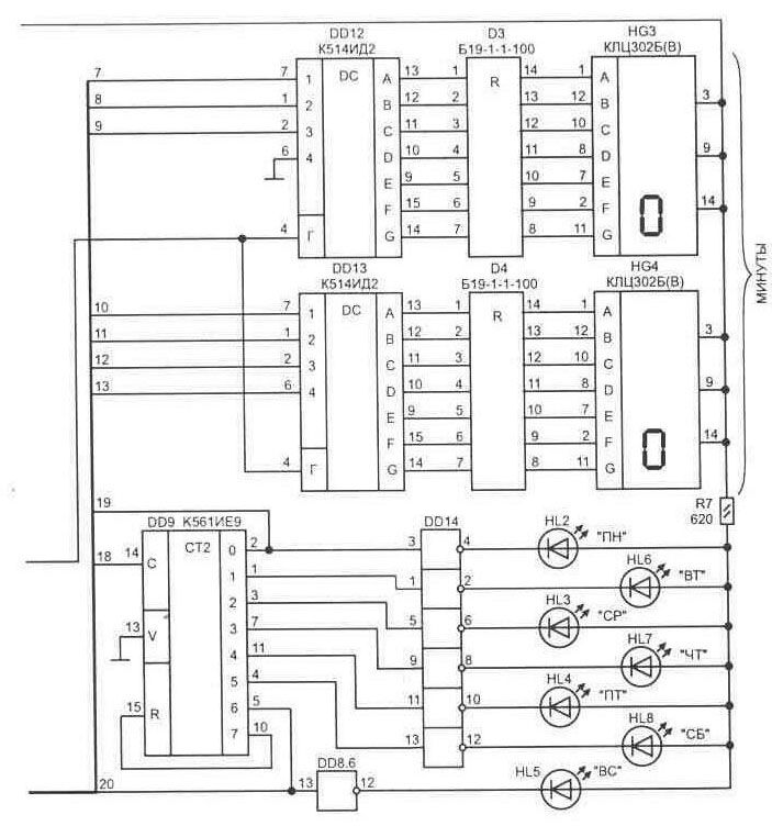
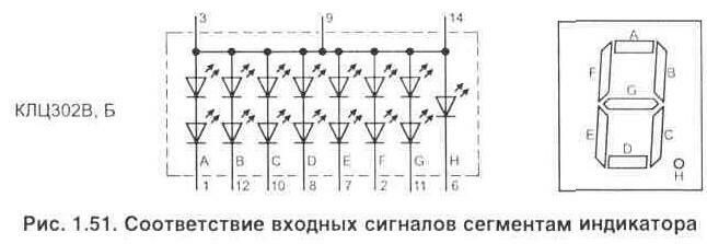
Switch SA1 allows you to check the operation of the clock and the installed control program in accelerated mode ("acceleration" position), when an increased frequency is used from the output DD2 / 6. The indication unit circuit consists of binary code decoders (DD10 ... DD13) into a seven-segment code necessary to control the operation of digital indicators based on LEDs. On fig. 1.51 shows the correspondence of input signals to indicator segments.
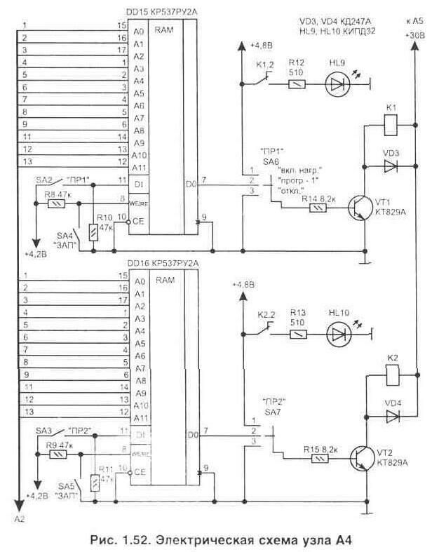
Resistor matrices D1 ... D4 limit the current through the indicator LEDs, and the diodes VD1, VD2 and the elements of the microcircuit DD13.1-DD13.2 provide the formation of a high-order quench signal in hours, when both inputs of DD10 have a zero level (at log. "0 "on DD10/4 the indicator will not light). For this reason, the F segment in the HG1 indicator can be omitted. The HL1 LED flashes at a frequency of 1 Hz, and only one of the HL2 ... HL8 LEDs will glow, corresponding to the day of the week. (Elements of the DD14 chip make it possible to provide the current necessary for the LEDs to glow). In the circuits for reducing the current consumed from the power source, pulses are supplied to the remaining inputs of the blanking indicators DD11.4 ... DD13.4, but due to the inertia of vision, this is not noticeable. Node for setting time intervals, fig. 1.52 is assembled on random access memory chips (RAM) from the 537 series. They are made using CMOS technology, which ensures long-term operation of the circuit from an autonomous power source (they retain the contents of the memory as long as there is power). The number of memory chips can be increased to the required number of control channels.
Since both load control channels are similar, let's consider the operation using one as an example. The scheme provides for an individual recording of information in each of the memory chips. The operation of this memory chip is explained in Table. 1.4. Table 1.4. Truth table for the 537RU2 chip
where x is any value of a logical signal, i.e. log. "0" or log. "one". The inputs of addresses A0 ... A11 receive a binary code from the outputs of the hour and minute counters, and if necessary, the days of the week. To record the desired program in canapes 1 (DD15), you must perform the steps in the following sequence: 1) switch SA1 is set to the "acceleration" position of the cycle - in this case, the signal to the input of the counter DD3/2 is supplied from DD2/6 and the watch goes through a daily cycle in about 12 minutes; 2) turn on the "-AP" switch, for channel 1 it will be SA4 - in this case, the O-U chip operates in the state recording mode at the DI input (log. "0"); 3) you need to wait for the moment when the clock indicates the required time to turn on the load and at this moment turn on SA2 ("PR1") - for the interval during which the load should work (log. "1" is recorded); 4) after the end of the recording of the entire cycle, return the SA4 switch to its original position (reading mode) and check the operation of relay K1 at the required time intervals by the clock; 5) return all switches to their original position (as shown in the diagram) and use the SB1 button to set the day of the week and the exact time. Now at the output D0 of the microcircuit (DD15 / 7) there will be a log level. "1" only during the desired time intervals. This signal opens the transistor VT1 and the relay K1 is activated, including the load on the sockets XS1.1 with its contacts K1. The scheme also provides for manual control of the load on at any time using three-position switches SA6 and SA7, fig. 1.52. LEDs HL9, HL10 are indicators of load activation in the corresponding channel. To power the device from the network, a power source is made according to the scheme shown in Fig. 1.53.
A unified transformer T1 is suitable, such as TPP255-127 / 220-50 or TPP255-220-50, but it can also be made independently using the calculation method given in the literature, for example L20, page 167. The current consumption in the circuit is 4,8 V is 0,35 ... 0,55 A, in a 30 V circuit - depends on the number of relays and for two usually does not exceed 120 mA. Clock for automatic control of devices 1-147.jpg A voltage stabilizer (DA1) was used to obtain high accuracy of the watch. It can also be assembled according to the diagram shown in the power supply section in fig. 4.3. Capacitors C8 and C9 are located near the logic circuits, and C7 is installed next to the stabilizer pins (it is better if oxide capacitors are used with tantalum ones). As a backup power source (G1), 4 batteries of the D-0,115 or D-0.26D type are suitable. Diode VD13 prevents the discharge of elements through the stabilizer circuit when the mains power is turned off. And in normal mode, the batteries are recharged through it. The SA8 switch is used to prevent a complete discharge of the battery when the watch is turned off for a long time. Power is supplied to the microcircuit pins in accordance with Table. 1.5. Table 1.5. The supply voltage on the microcircuits
The printed circuit board for clock assembly was not developed. Installation is carried out on a universal breadboard (it is better if it provides for the installation of any microcircuits - with a planar and conventional pinout). Structurally, nodes A1 and A2 are conveniently located on the same board, connected to the display unit A3 through a 32-pin connector (for example, type RP 15-32). Batteries are fixed in such a way that they are easily accessible, since once a year protruding deposits must be removed from the surface of the cells. It is possible to reduce the dimensions of the board and the entire device if, instead of the 561 series, similar microcircuits with a planar pin arrangement from the 564 series are used, but they are much more expensive. To assemble the device, resistors are suitable for any type. Resistor assemblies D1 ... D4 can be replaced with conventional resistors with a resistance of 100 ... 120 Ohms and a power of 0,125 ... 0,25 W. Capacitors C1, C2 must have a small TKE (M47, M75); C-type K10-17; oxide C4 ... C8 - K53-1. The ZQ1 quartz resonator will suit any type - they are widely used, as they are specially produced for use in watches. Diodes VD1, VD2 fit any pulse; rectifier diodes VD3 ... VD12 can be of any type for a current of at least 1 A, but it is better to use KD257 or KD258 (the last letter in the designation for this circuit can be any), since they have a very useful property: in case of a malfunction in the circuit, the diodes burst during overload and break the circuit, acting as a fuse, which makes such a power source safe even in an emergency. LEDs HL1...HL10 are best used from the KIPD05A series (B, C - with different glow colors) - they glow quite brightly at a current of about 1 mA. Digital indicators HG1...HG4 can be used by ALS321B or ALS324B, but they have a smaller height of digits (8 mm) in contrast to those indicated in the diagram (18 mm). Chip DA1 must be installed on the radiator. Memory chips DD15, DD16 are replaced by 537RU6. Relays K1, K2 are used by Polish production, but many others are suitable for the operating voltage of the winding 24 ... 27 V and allowing the passage of current through the contacts 5 A. Microswitches SA1 ... SA5 type PD9-2 or PD9-1; SA6, SA7 - type PD21 -3. When initially checking the operation of the circuit, it is better to power it from a laboratory source, controlling the current drawn. Setting up the device with proper installation consists in installing a voltage of 4,8 V at the output of the power source and checking the operation of the programs stored in the memory. To obtain high accuracy of the clock, fine tuning with the help of capacitor C1 of the frequency of the self-oscillator according to the frequency meter will also be required. The frequency can be controlled at the output of DD2 / 13 - it must correspond to 32768,0 Hz. It is possible to fine-tune the oscillator even without a frequency meter, controlling the deviation of the clock in the second hand on the TV for a month, but this will take quite a long time. Setting any time can be done without using the SB1 button. To do this, you need to set the SA1 switch to the "acceleration" position and wait until the indicator shows the desired numerical value, return the switch to its normal position. But this method of setting the time is less accurate, since in this case the second pulse counters can have an arbitrary number value.
Machine for thinning flowers in gardens
02.05.2024 Advanced Infrared Microscope
02.05.2024 Air trap for insects
01.05.2024
▪ New Schottky diodes from VISHAY ▪ Bacteria help produce nanomaterial for computers
▪ site section Power supplies. Article selection ▪ article Silence is a sign of consent. Popular expression ▪ How did the Grand Canyon form? Detailed answer ▪ article Planer Shavings. home workshop ▪ article Decoder logic analyzer. Encyclopedia of radio electronics and electrical engineering
Home page | Library | Articles | Website map | Site Reviews
www.diagram.com.ua | |||||||||||||||||||||||||||||||||||||||||||||||||||||||||||||||||||||||||||||||||||||||||||||||||


 Leave your comment on this article: