|
|


 Arabic
 Bengali
 Chinese
 English
 French
 German
 Hebrew
 Hindi
Hindi Italian
 Japanese
 Korean
 Malay
Malay Polish
 Portuguese
 Spanish
 Turkish
 Ukrainian
 Vietnamese
|
ENCYCLOPEDIA OF RADIO ELECTRONICS AND ELECTRICAL ENGINEERING High frequency fluorescent lamp power supply. Encyclopedia of radio electronics and electrical engineering
Encyclopedia of radio electronics and electrical engineering / Lighting Traditional circuits for switching on fluorescent lamps are designed to be powered by alternating current of industrial frequency. Today, it is becoming more and more common to power such lamps with increased frequency current, which eliminates flickering and increases start-up reliability. There is no need for large-sized capacitors and chokes on steel magnetic circuits, which often emit an unpleasant buzz. The proposed high-frequency unit is small in size, contains a minimum number of winding elements, is simple and accessible for repetition. The diagram of a block designed to power an OSRAM L13W fluorescent lamp with a bulb diameter of 16 mm is shown in fig. 1.
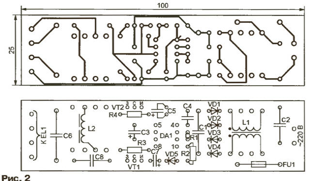
Through the fusible insert FU1 and the noise suppression filter C2L1, the mains voltage is supplied to the diode bridge VD1-VD4. The inverter on the IR2153 (DA1) chip and IRF840 (VT1, VT2) field-effect transistors converts the rectified voltage into symmetrical rectangular pulses. Detailed information about the IR2153 chip and IRF series transistors can be found on their manufacturer's website. . The pulse frequency depends on the values of the elements of the timing circuit R1C4 and in this case is equal to 33 kHz. Pauses of 1 μs are automatically maintained between the pulses at the LO and BUT outputs of the microcircuit that controls the field-effect transistors VT2 and VT1,2. This prevents the transistors from simultaneously opening with "through" current flowing through them. The supply voltage of the DA1 microcircuit is supplied to its output 1 through a quenching resistor R2, and the internal zener diode does not allow an increase in the potential difference between terminals 1 and 4 above 15,6 V. In operating mode, it is 9-10 V. The output voltage of the inverter is supplied to the lamp EL1 through the coupling capacitor C8 and the ballast choke L2. The purpose of the latter is similar to the usual ones used in lamp supply circuits with a frequency of 50 Hz, but since the frequency in this case is much higher, the inductance of the inductor, its dimensions and weight are much less. Capacitor C6 forms a circuit for heating the filaments of the lamps. The block is assembled on a printed circuit board (Fig. 2) with dimensions of 100x25 mm.
Capacitors C1, C2, C8 - K73-17, C4 and C6 - K78-2, oxide - K50-35. Inductors L1 and L2 are wound on magnetic cores Sh4x4 made of M2500NMS or M2000NM ferrite. The windings of the inductor L1 contain 200 turns of PEV-2 wire 0,1 mm each and are wound in insulated frame sections. The halves of the magnetic core of this inductor are glued together without a gap. The winding of the inductor L2 is 220 turns of wire PEV-2 0,22 mm. In its magnetic core, a non-magnetic gap is required, the thickness of which (0,3 ... 0,5 mm) is selected experimentally according to the brightest glow of the lamp. Diodes VD1-VD5 can be replaced by any others with a current of at least 0,5 A and a reverse voltage of at least 400 V, for example, KD209A-KD209V, KD226V-KD226D. In this case, the dimensions of the printed circuit board will have to be increased. Replacing IFR840 transistors is possible with IRF830, IRF820, but will lead to a deterioration in their thermal conditions due to the greater channel resistance. By making small changes to the unit, you can also power more powerful lamps from it. For example, in fig. 3 shows how to connect two LDC-20-2 lamps. In this case, the cross section of the magnetic circuit of the inductor L2 is increased to 6x6 mm, the wire diameter is up to 0,4 mm, and the number of turns is reduced to 120. Inductor L3 is identical to L2. The L1 choke is also wound on a similar magnetic circuit, increasing the wire diameter to 0,3 mm.
The capacitance of capacitors C1 and C3 (see Fig. 1) is increased to 0,68 and 10 μF, respectively, and transistors VT1 and VT2 are supplied with heat sinks with an area of at least 40 cm2. It is also necessary to increase the operation current of the fuse-link FU2 to 1 A, and install a 4,7 Ohm resistor with a power of at least 5 W (for example, wire) into the gap of one of the network wires to limit the charging current of the capacitor C3 at the moment the unit is turned on. Author: A. Tarazov, St. Petersburg
Machine for thinning flowers in gardens
02.05.2024 Advanced Infrared Microscope
02.05.2024 Air trap for insects
01.05.2024
▪ Electric coupe-crossover Skoda Enyaq Coupe iV ▪ Sedentary work strengthens mental abilities ▪ Microchip MCP1631 PWM Modulators
▪ radio section of the website. Article selection ▪ article by Woody Allen. Famous aphorisms ▪ article Why do people faint? Detailed answer ▪ article The machinist of the plastering station is mobile. Standard instruction on labor protection ▪ article Experiments with copper wire. Chemical Experience
Home page | Library | Articles | Website map | Site Reviews
www.diagram.com.ua |


 Leave your comment on this article: