|
|


 Arabic
 Bengali
 Chinese
 English
 French
 German
 Hebrew
 Hindi
Hindi Italian
 Japanese
 Korean
 Malay
Malay Polish
 Portuguese
 Spanish
 Turkish
 Ukrainian
 Vietnamese
|
ENCYCLOPEDIA OF RADIO ELECTRONICS AND ELECTRICAL ENGINEERING Small dynamic installation Omega. Encyclopedia of radio electronics and electrical engineering
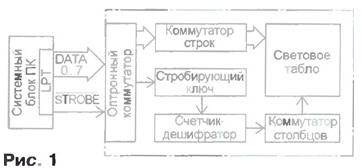
Encyclopedia of radio electronics and electrical engineering / Lighting Dynamic information display devices are widely used in street advertising, as well as in enterprises, educational institutions, shopping centers and other institutions where there is a need to familiarize the public with fleeting data and dynamic information flows. Amateur developments of this purpose have been repeatedly described in periodicals. Their main disadvantages, in addition to significant cost, are dependence on data programmed in ROM chips, the inability to quickly change the displayed information, and in some cases the need to use rare components. The proposed device is a prefix to a computer, made on an affordable element base and has a fairly wide operational capabilities. The small-sized dynamic unit (MDU) "Omega" together with the software package allows you to organize the output of displayed information both in symbolic form from a set of typical symbols provided by the character generator, and in graphical form, which is specified by the user from an arbitrary set of pixels. The MDU operates under the control of an IBM-compatible personal computer (PC) with the MS DOS or Windows operating system. The device has a compact size, easy to operate, easy to install and does not require special knowledge to use. Unlike industrial prototypes, in a minimal configuration (based on a PC with an 80286 processor) it has a low cost. The block diagram of the device is shown in fig. one.
The LPT port of the PC controls its operation. In this case, an eight-bit data bus is used, which determines the number of LEDs in the familiarity vertically or the number of lines. The data bus is controlled through port address 378h. By setting a signal code at this address, the value of which can range from 0 to 255, you can set any combination of high and low levels on the LPT data bus of the port. The signal code from the LPT port goes to the row optocoupler, which provides any combination of vertically on and off LEDs. For switching and vertical columns and creating a dynamic horizontal sweep, the STROBE signal is used, which is generated by software when accessing the port at address 37Ah. Through the strobe key, the signal is fed to the counter-decoder synchronously with the change in signals on the data bus. The counter-decoder controls the sequential operation of the switches of the vertical columns of LEDs, creating a horizontal sweep. Depending on the needs and the required information content of the device, the counter-decoder can be 8-, 16-, 32-, 64- or 128-bit, which provides a proportional change in the number of vertical columns and, accordingly, the length of the light-emitting screen. In the described device, an LED display is used, consisting of 32x8 elements (256 LEDs). The schematic diagram of the device is shown in fig. one.
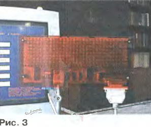
To ensure galvanic isolation and protection of the PC from extra currents that can be induced in the connecting wires at a large distance of the MDU from the system unit and operation in adverse electromagnetic conditions, the operation of the device is controlled through optocouplers U1.1 and 1U1-8U1 (U2.1-U5.2). From the data bus, the signal generated by the software at the output of the LPT port through the XS1 connector is fed to the input of the row switch, made on optocouplers 1U1 8U1 and transistors 1VT1 8VT1. As a result, the corresponding transistors come off and the groups of LEDs included in their emitter circuits, forming vertical columns, are connected to the power supply circuit of the device through current-limiting resistors 1R3 -8R3. A change in the state of the data bus is accompanied by the appearance of a clock pulse on the Strobe LPT line of the port. When this pulse passes through the optocoupler U1.1, the key on the transistor VT1 is activated, which causes a change in the state of the counter DD1. Together with the DD2 counter and the DD3.1 inverter, it ensures the proper operation of the DD4 and DD5 decoders and the alternate activation of their outputs connected to the vertical column switch, made on transistors VT2 -VT33. As a result, a horizontal sweep is created: when the opening time of the keys of the row commutator and the switching key of one or the other vertical column coincide, the cathodes of the corresponding LEDs are connected to the power source of the device and ignite. As the next clock pulse occurs on the Strobe line and the signals on the data bus change, the LEDs for the next column light up, and so on. The device provides output of text information of arbitrary length from a text file, as well as user-created graphic images from a data file. You can analyze the operation of the device software by considering the following fragments of programs written in the TurboBASIC language. The programs are designed to connect the MDU to the LPT1 port with the address 378h, while the horizontal sweep is controlled via the Strobe line when accessing the 37Ah port. ' Alternately switching on the elements ' items of one vertical column out &h378,1: delay .3 out &h378,2: delay .3 out &h378,4: delay .3 out &h378,8: delay .3 out&h378,16: delay .3 out &h378,32: delay .3 out &h378,64: delay .3 out &h378,128: delay .3 out &h378,0: delay .3 end ' Alternately switching on the elements ' items of one vertical column for i = 1 to 10 for j-0 to 7 out &h378,2^j delay .05 next j next i end ' Filling with glowing ' elements of one column for i = 0 to 255 out&h378,i deJay.028 Next end ' "Running Column" effect for e=0 to 31 out&h378,255 out&h37A,0: for q=0 to 3100: next q out &h37A, 1: for w=0 to 3100: next w next e end ' "Running Diagonal" effect for i=1 to 10 for j=0 to 7 out &h37A,0: out &h378,24 for k=0 to 80: next k out &h37A,1: for 1=0 to 80: next 1 next j next i end ' Glow all elements for e=0 to 3100 out&h378,255: for r=0 to 10: next r out&h37A,0: for q=0 to 1: next q out&h37A. one: for w=0 to 10: next w next e out&h378,0 end Device software developed by the author The device is mounted on a printed circuit board with dimensions of 250x110 mm made of double-sided foil fiberglass (Fig. 3).
The board drawings are posted on the Internet at the same address as the software. During installation, it should be noted that the conclusions of some parts must act as jumpers connecting the printed conductors on different sides of the board, so they must be soldered to the printed conductors of both sides. Blocking capacitors C2-C6 are soldered directly to the power pins of the microcircuits DD1, DD2 and DD4, DD5. After the installation is completed, the LEDs are covered with a red transparent organic glass plate. To operate the device in the minimum configuration, it is enough to have a PC system unit based on the 80286 processor with a keyboard and a floppy drive (a monitor is not required). The MDU is powered from an autonomous source with an output voltage of 5 V at a current of up to 0,5 A. You can increase the brightness of the LEDs by reducing the resistance of the resistors 1R3 -8R3, however, it is not recommended to choose less than 20 Ohms, since the average value of the current through the LED may exceed the maximum allowable. The proposed circuitry approach allows, if necessary, to create a device with a number of vertical columns from 8 to 128, while the number of light-emitting elements can vary from 64 to 1024. However, it should be noted that with more than 64 columns, the brightness of the glow decreases. In this case, it is desirable to use light-emitting diodes with a light-emitting surface of a rectangular shape. Author: O.Zhelyuk, Rivne, Ukraine
Machine for thinning flowers in gardens
02.05.2024 Advanced Infrared Microscope
02.05.2024 Air trap for insects
01.05.2024
▪ A man's character does not depend on his brothers and sisters ▪ Smartphone vibration motor for wiretapping ▪ Meat steak grown from tenderloin ▪ Spent spacecraft stages are returning
▪ section of the site Calls and audio simulators. Article selection ▪ article Our brother Isakiy. Popular expression ▪ article What are primary colors? Detailed answer ▪ article Feeder driver. Standard instruction on labor protection
Home page | Library | Articles | Website map | Site Reviews
www.diagram.com.ua |


 Leave your comment on this article: