|
|


 Arabic
 Bengali
 Chinese
 English
 French
 German
 Hebrew
 Hindi
Hindi Italian
 Japanese
 Korean
 Malay
Malay Polish
 Portuguese
 Spanish
 Turkish
 Ukrainian
 Vietnamese
|
ENCYCLOPEDIA OF RADIO ELECTRONICS AND ELECTRICAL ENGINEERING Encoder and decoder for the security alarm radio channel. Encyclopedia of radio electronics and electrical engineering
Encyclopedia of radio electronics and electrical engineering / Safety and security The magazine returned to the topic of radio channels for burglar alarms more than once. The use of radio communication in security equipment is often convenient, and sometimes the only way to transmit an alarm signal. This article describes another version of the encoder and decoder for such a system. Quite a lot of time has passed since the radio became more accessible for known reasons. And not only for those who were originally called radio amateurs, but also for those who use it for practical purposes: radio remote control, personal radio communications, radio beacons, etc. One of the interesting areas of application (and recently relevant) is protection of various remote objects, in particular, vehicles. The journal "Radio" published several designs intended for this purpose, including Yu. Vinogradov's radio channel [1-3] and S. Biryukov's radio watchman [4]. In terms of their complexity and in many respects the element base, these two designs are similar, although in practical terms they differ somewhat. This mainly applies to work in conditions of intense radio interference. If in the first case there is a high probability of not receiving an alarm signal, in the other case, false alarms will annoy the owner, which also reduces the reliability of protection. In addition, the presence of constant signals on the air can attract the attention of radio hooligans. In any case, it is up to the radio amateur to decide which design to prefer. The author of this article opted for the publication [1-3]. The encoder and decoder of the radio channel have undergone a change. The encoder scheme [1, Fig. 1], according to the author, contains "extra" details that unreasonably limit the possibilities of using the radio transmitting unit. So, the presence of a "one-time" trigger on the elements DD4.3 and DD4.4 obviously implies working only with contact sensors and requires the intervention of the owner after each actuation of the watchman. It is much better to make a radio transmitting unit as an addition to a burglar sound alarm. Such alarms, as a rule, include the necessary components, including executive ones (relays, transistors, thyristors, etc.). This will allow the owner, depending on the conditions, to choose the necessary mode of operation of the watchman, for example, use an audible alarm during the day, which is also intended for an intruder, and switch to "silent" protection at night. What has been said, however, does not mean that the radio transmitting unit cannot be used independently. In the decoder [1, Fig. 2], there are a significant number of connections between logical elements that are part of different microcircuits, which makes it difficult to create a compact printed circuit board. And although in the preface to article [3] it is stated that the owner can carry the radio receiving unit with him, it cannot be called "pocket" in any way. In addition, it does not provide for the internal antenna necessary in such cases, although its possible design is given. All of the above prompted the author of the article to create, based on the design of Yu. Vinogradov, his own radio channel with radio signal encryption. The dimensions of the radio transmitting unit (without antenna) are reduced by almost 3 times, and the radio receiver with a magnetic antenna - by 2 times. The encoder circuit (with transmitter) is shown in fig. one.
Functionally, it fully corresponds to the analogous node of Yu. Vinogradov [1]. The maximum possible number of cipher combinations was also saved - 16384. The change affected only the transmission speed of the radio message * - the frequency of switching channels of the multiplexer (familiarity) was doubled while maintaining the frequency of the clock generator. This was done, on the one hand, for the convenience of "wiring" the printed circuit board, and on the other hand, because of the features of the counter used. However, there is no reason to fear that the bandwidth of the radio emission will go beyond the allowed limits or that the bandwidth of the piezoceramic filter in the radio receiver will not be enough. As an example, we can refer to the design [4], where the modulation frequency of the radio transmitter is even higher. As can be seen from the diagram, the encoder is assembled on only two microcircuits from the original CMOS 4000 series [5]. The CD4060 (DD1) microcircuit is similar in its internal structure to the 14-bit counter CD4020 (K561IE16), but unlike it, it has outputs from buffer elements at the input for building a generator. Accordingly, it has no outputs from a larger number of digits - in addition to the second and third digits, the first and 11th ones also have no outputs. The CD4067 (DD2) microcircuit is a 16-channel multiplexer-demultiplexer controlled by a four-bit binary code and can replace two K561KP2 (KR1561KP2) microcircuits. In the encoder circuit in Fig. 1, the reference designation of the inputs A-D of the DD2 chip and the channel numbers X0-X15 is saved. When developing the printed circuit board, the order of connecting the AD inputs to the outputs of the DD1 counter was changed, so the switching of channels (familiarity) in time occurs exactly in the sequence indicated in the diagram (from top to bottom). In general, it should be noted that the designation of AD inputs and channel numbers is rather conditional, since the public key number is determined by the truth table depending on the address code and nothing else. The operation of the proposed encoder is almost the same as that described by Yu. Vinogradov, although it has some peculiarities. First of all, this refers to the formation of a pause between radio messages. The original source [1] does not say anything about its purpose, but, obviously, a pause is necessary to highlight the start bit against the background of a cipher combination containing largely similar information. Therefore, for reliable joint operation of the encoder and decoder (first of all, when the transmitted and received information do not match), it is desirable that the pause in duration should not be less than the radio message. Since the counter DD1, as already mentioned, does not have an output of the 11th bit, the pause duration is chosen to be equal to the radio message itself (15,6 ms). Another feature of the encoder is that it, like the transmitter, is de-energized in standby mode. The alarm mode is provided by supplying voltage to the radio transmitting unit (including the encoder), which made it possible to reduce the number of external communications. To set the counter DD1 to its initial state is the circuit C12R8. It also provides a delay in the start of the radio transmission of the alarm signal for the time required for the transmitter generator to enter the operating mode, and allows the unit to be used directly with contact sensors without taking additional measures to suppress contact bounce. Resistors R9, R10 and a quartz resonator ZQ2 are elements of the internal oscillator of the DD1 chip. Diode VD1 protects the device from incorrect connection of the polarity of the voltage source. On fig. 2 shows a possible version of the printed circuit board of the radio transmitting unit containing the considered encoder. The encoder is conventionally separated from the transmitter by a dotted line. The board is made of one-sided foil fiberglass. Short inter-element connections and a well-thought-out arrangement of parts make it possible to dispense with shielding foil.
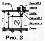
The radio transmitter uses small-sized imported resistors, but domestic ones (MLT, S2-23, etc.) are also suitable when installed vertically on the board. A thin rubber gasket pre-lubricated on both sides with 88N glue is placed between the quartz resonator and the board. The resonator is fastened with an insulated wire, which is also an electrical jumper. If the resonator leads are rigid (PK169, PK373), they must be shortened to the minimum length, and the connection to the printed circuit board should be made using a thin wire or use the leads of the resistor R3. The high-frequency antenna socket X1 is installed on the board using a self-made U-shaped clamp made of wire with a diameter of 2 mm. At its ends, an M2 thread is cut for fixing nuts. In the side faces of the nest, which have a thread, it is necessary to grind two grooves with a round file to a depth of 1 ... 1,5 mm under the clamp. For the manufacture of this part, instead of wire, it is convenient to use tightening pins from the PG-3 biscuit switch. The output of the socket is connected to the board with a conductor. The transmitter has a continuous emission mode. Since this mode is used quite rarely (mainly for setting up the radio channel as a whole), it is implemented somewhat unusually (Fig. 3).
The body of the transmitting unit is made of thin tinned sheet and is electrically connected to a common wire. A hole with a diameter of 4 mm was drilled in the housing cover above the rack of the L3 coil frame. A M2,5 nut is soldered to the inside of the cover coaxially with the hole. A screw is screwed into the nut from the outside. Since the aforementioned rack of the coil frame is electrically connected on the board to the collector of the transistor VT3 (see Fig. 1), when the screw is screwed in, the collector will close to the case, which corresponds to the continuous radiation mode. On the protruding part of the rack, it is necessary to "plant" a drop of solder, and put a washer made of elastic material (for example, porous rubber) under the screw head. Its thickness should be such that, in the absence of contact, it is slightly compressed to prevent spontaneous loosening of the screw. Springs can also be used. Reliable contact is provided by some elasticity of the body material. It is desirable to use a copper screw. Capacitor C10 - K53-1A, the rest - KM or K10-176. Quartz resonator ZQ2 - in a flat case, slightly smaller than the common RV-72. It is possible to use a resonator from a wrist watch in a miniature cylindrical case. The selected cipher combination is set by connecting the pins of the DD2 chip to the corresponding printed conductor using a drop of solder. The encoder does not need to be adjusted. With serviceable parts and no installation errors, it starts working immediately when the supply voltage is applied. With the help of an oscilloscope, at pin 9 of the DD1 microcircuit, one can observe rectangular pulses of the clock generator, and at pin 1 of DD2 (CT) - the typed cipher combination. The decoder circuit is shown in fig. 4. Its main difference from that described by Yu. Vinogradov lies in the node for comparing the cipher combination received from the air with that installed in the decoder. The comparison takes place almost instantly on the positive edge of the counter pulse in the middle of each familiarity (decoder). This made it possible to largely neglect the disparity in the frequencies of quartz resonators in the encoder and decoder, as well as to slightly increase the noise immunity. In addition, such a construction turned out to be easier to implement and required a smaller number of microcircuits.
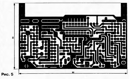
When the decoder is powered on with a high-level pulse through capacitor C1, the triggers of the DD2 microcircuit are set to state 1 (regardless of the state of other inputs). A high level from the output of the trigger DD2.2 resets the counter DD4 and prohibits its further operation. Immediately after this, a low level appears at the output of the trigger DD2.1, since its input R remains high. This allows the operation of the trigger DD2.2 clock input C. The decoder goes into standby mode. In this mode, the X0 channel of the DD5 multiplexer is closed, on the AD address inputs of which the combination is 0000. Accordingly, the remaining channels are open, including XI5, and the output 9 of the DD3.3 element is low (the SA1 toggle switch is closed, since the power is on). Alarm node [1] is not working. For the clock generator, assembled on the elements DD1.1 and DD1.3, the low level at pin 8 DD1.3 is permissive, so in standby mode it generates rectangular pulses. When an alarm signal appears on the air, more precisely, the start bit of the cipher combination installed in the radio transmitting unit, a high level will appear at the output of the DD1.4 element. Trigger DD2.2 will switch and enable the counter DD4, as well as trigger DD2.1 on input C. Simultaneously with the operation of the counter, the enumeration of the cipher combination (familiarity) by the DD5 multiplexer begins in the sequence indicated in the diagram (top to bottom). Its comparison with the one received from the air takes place on the element DD1.2. The result of the comparison (0 if the same and 1 if the signals are different) is transmitted to the information input D trigger DD2.1. At the input C trigger in the middle of each familiarity receives the fronts of the pulses from the output 5 of the counter DD4. Switching the trigger to a single state is possible only if the signals do not match in any place. If the received and installed cipher combination does not match, a process similar to entering the standby mode occurs, with the only difference that the time delay no longer depends on the charging time of the capacitor C1, but is determined only by the time parameters of the microcircuits used. The complete match of the set cipher combination with the one received from the air means that there was a search of all the familiarity places by the DD5 multiplexer. Channel X15 will open last when combined at address inputs 1111. In this case, the input of the alarm node and output 8 of the DD1.3 element with the contacts of the SA1.1 switch closed will be connected to the voltage divider R1R2. The voltage on this divider is approximately 5/6 of the supply, which corresponds to a high logic level. An alarm will sound and the clock generator will stop. This state will be maintained until the SB1 button is pressed. The use of the SA1 switch with two groups of contacts expands the functionality of the radio guard. One group of contacts (SA1.2) is designed to turn off the power of the receiving unit when it is used in a portable battery-powered version, and the second group (SA1.1) is used to disable the alarm mode latching when powered by an external unit connected to the XS1 connector. In this case, the state of contacts SA1.2 does not matter, since the battery is switched off by contacts 2 and 3 of the socket. In addition to a stabilized power supply for a voltage of 6 ... 9 V, the external unit may contain other electronic devices, for example, a high-volume alarm unit with turning off other sound sources, a recorder of the time and number of operations [6] or a device for transmitting an alarm message by telephone [7]. Structurally, the block can be designed, for example, in an electronic clock, radio receiver, etc., which, by the way, can themselves have signal nodes. When the contacts of the switch SA1.1 are open, the alarm signal is not fixed in the decoder (this function is performed in one form or another by an external unit), since the clock generator continues to work. In this case, the decoder will return to standby mode automatically (at the first mismatch of the cipher combination), as soon as "silence" is restored on the air. Naturally, in the watchdog device with which the radio transmitting unit will work, it is necessary to provide for a similar mode (for example, limit the alarm signal in time). Please note that the input impedance of the external device connected to pin 5 of connector XS1 must be large enough not to bypass the voltage divider R1R2. It is allowed to reduce the voltage on the divider to 0,7 supply. Note that it is possible to automatically turn off the decoder alarm unit when using an external unit. To do this, it is enough to connect pin 8 of the DD3.3 element with pin 4 of the XS1 connector, by shunting it with an additional resistor to a common wire. A drawing of the printed circuit board of the radio receiving unit with a decoder is shown in fig. 5.
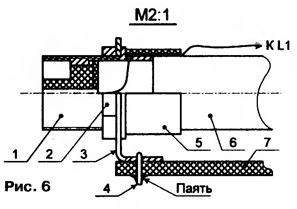
The board is made of double-sided foiled fiberglass, but the use of one-sided is not excluded, since a small number of printed conductors on the part installation side can be made with a thin mounting wire. Wire jumpers must be inserted into the holes of the square contact pads and soldered on both sides of the board. The designations of the receiver parts (in the figure it is separated from the decoder by a dotted line) correspond to the receiver circuit in [8]. For the possibility of autonomous use of the unit, a magnetic antenna WA1 was used [3, fig. 7] with a coupling coil L1 and a high-frequency connector X1 for connecting an external antenna. Additionally, the board provides for the installation of the following parts (shown by dashed lines): a trimmer capacitor C1' (connected in parallel with C1), an additional blocking capacitor for powering the input stage C3' and a single oscillating circuit L5C21C22 (to increase the selectivity of the receiver [3]). Minor changes have been made to the receiver itself. It is necessary to swap the resistors R10 and R11, Piezoceramic filter ZQ2 - FP1P1 -060.1. Instead of the voltage comparator K554SAZ (DA3), K521SAZ with the corresponding pinout was used. It is also possible to use 554SAZ, but in an 8-pin package. It turned out that the reverse order of the conclusions (clockwise in the top view) is preferable. Therefore, this microcircuit is not installed on the board as standard. There are several options. The easiest way is to solder the chip from the side of the printed conductors. The second option is to bend the leads in the opposite direction. In the case of a metal case, this is preferable (you only need to put insulating tubes on the leads). Conclusions 1, 4, 6, 9, 14 of the DA1 (K174PS1) microcircuit are connected inside the crystal to each other - a common wire is connected to them on the board. Free conclusions 7 and 8 of the DA2 chip (K157XA2) must be removed, and a jumper should be soldered instead. By the way, the recommendations for the use of this microcircuit [9] indicate the undesirability of the presence of any electrical signals on these conclusions. Coils L1 and L2 are wound on a ferrite rod with a diameter of 8 and a length of 80 mm. Mounting options for the magnetic antenna and small-sized RF connector X1 (SR75-104 and SR75-103) are shown in fig. 6.
Connector 1 is fixed with a nut 2 on an angle bracket 3 made of thin sheet material. It is convenient to use tin (it can be cut with ordinary scissors), having previously drilled a hole with a diameter of 8 mm for the connector. Such a bracket (its width is 12 mm) can be soldered to the board using a wire clamp 4. The connection of the ferrite rod 6 with the connector is carried out using a sleeve 5 machined from a suitable non-metallic material. In the simplest case, this can be a polyvinyl chloride tube, put on with an interference fit or glued. The wire from the central terminal of the connector is passed through a hole in its body (intended for soldering the cable braid) and laid either under the tube or over it. In the case of using only an external antenna, the coils L1, L2 can be installed in place of the capacitors C1' and C1 by soldering the capacitor C1 directly on the racks of the coil frame L1. Capacitor C6 in the decoder is K53-1A, its metal case also serves as a screen between the digital part and the radio receiver. Not shown in Fig. 4 pins 1, 5, 14, 15 of the DD4 chip (KR1561IE20) must be removed or countersinked for them on the opposite side of the board. Under conclusions 4,11 (DD1), 12 (DD2) and 9 (DD4), contact pads on the same side should not be made. The piezo emitter HA1 (ЗП-18) must be modified before installation on the board. To the base of the piezoelectric element, taken out of the housing, the L-shaped wire rack is soldered perpendicularly. It is inserted into the board hole and soldered so that the piezoelectric element does not touch the parts. The lining of the piezoelectric element is soldered to the board using a flexible thin conductor. This "free" design contributes to increased sound output. When using a magnetic antenna, the housing of the receiving unit must be made of a "radio transparent" material. The case from the designer "Youth KP 101", well known to radio amateurs, will do. The operation of the decoder can be checked by disconnecting the output of the DD1.4 element from other elements. To do this, it is convenient to carry out the conductor from the installation side of the parts between terminals 11 and 6 of the DD1 microcircuit with a mounting wire. Pin 6 DD1 or pin 11 DD2 connected to the control point (CT) in the encoder and close the contacts of the switch SA1. When the supply voltage is applied to the encoder, an alarm intermittent signal should be heard in the decoder. With a clearly insufficient volume, you can try to pick up a resistor R6. * A radio message here should be understood as the broadcast of one cipher combination, divided into 16 (according to the number of multiplexer channels) identical time intervals (familiarity), each of which is characterized by the presence or absence of high-frequency radiation. The first two familiar spaces are occupied by service information necessary to start the decoder and synchronize it with the encoder. Literature
Author: A.Martemyanov, Seversk, Tomsk region
Machine for thinning flowers in gardens
02.05.2024 Advanced Infrared Microscope
02.05.2024 Air trap for insects
01.05.2024
▪ New exoplanet search tool launched ▪ ON Semi Launches New 600V N-Channel MOSFETs ▪ Motorcycle helmet with mirrors
▪ section of the site Microcontrollers. Article selection ▪ article Fishing in troubled waters. Popular expression ▪ article How do Arabs write and read numbers? Detailed answer ▪ article Work on cassette-knife folding machines. Standard instruction on labor protection
Home page | Library | Articles | Website map | Site Reviews
www.diagram.com.ua |


 Leave your comment on this article: