|
|


 Arabic
 Bengali
 Chinese
 English
 French
 German
 Hebrew
 Hindi
Hindi Italian
 Japanese
 Korean
 Malay
Malay Polish
 Portuguese
 Spanish
 Turkish
 Ukrainian
 Vietnamese
|
ENCYCLOPEDIA OF RADIO ELECTRONICS AND ELECTRICAL ENGINEERING Laser pointer in burglar alarm. Encyclopedia of radio electronics and electrical engineering
Encyclopedia of radio electronics and electrical engineering / Safety and security Attention! Laser radiation is harmful to the eyes and can damage the skin. When working with laser radiation sources, avoid hitting the beam on people. Recently, laser pointers have become widespread. They are sold in shops and radio markets, and their cost is low. The narrow beam emitted by such a pointer can be used in security equipment. This article is devoted to this. Infrared lasers with their invisible radiation are widely used in professional security systems. Unfortunately, radio amateurs still have only one type of laser emitter - a red glow pointer. It has a low radiation power, no more than a few milliwatts, is safe for people and animals, but it is not recommended to direct laser radiation directly into the eyes. The radiation of a laser pointer in a pulsed mode is so subtle that in stealth it is not much inferior to infrared emitters, and in terms of system alignment it has a clear advantage over them. A diagram of a pulsed emitter based on a laser pointer is shown in fig. one.
The repetition rate of laser flashes sets the generator, assembled on the elements DD1.1 and DD1.2. With the ratings indicated on the diagram, this frequency is approximately equal to 5 Hz. Due to the differentiating circuit C2R3, short pulses with a duration of 1.4 μs are formed at the output of the DD10 element. These pulses open the transistor VT1 to saturation, and the VI laser generates flashes of the same duration. To reduce the overall power consumption of the emitter, a resistor R6 was introduced, which lowers the supply voltage of the DD1 microcircuit to 3 V. The SA1 toggle switch is designed to turn on the continuous radiation mode during adjustment. The device is assembled on a printed circuit board (Fig. 2) from double-sided foil fiberglass 1 mm thick. The foil under the parts is used only as a common wire. Connections to it of the conclusions of capacitors, resistors and other elements are shown in blackened squares; a square with a light dot in the center shows the "grounding" of pin 7 of the DD1 chip.
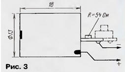
All resistors - MLT-0,125. Capacitors C1 and C2 - KM-6, C3 and C4 - K53-30. The laser pointer needs to be shortened. Departing from the "window" by 18 mm (the cone-shaped tip is generally removed), its body is carefully filed in a circle and the battery part is separated. The button is dismantled from the laser board that has now become accessible, and the excess board is bitten off (Fig. 3).
All structural elements of the emitter are mounted on a plate 51x30 mm, cut from a sheet of high-impact polystyrene 1,5 ... 2 mm thick (Fig. 4). Here: 1 - laser in the socket-clip; 2 - partition for the battery; 3 - printed circuit board; 4 - printed circuit board retainer glued to the partition (two strips of polystyrene); 5 - a polystyrene support 10 mm high glued to the base with a thread for an M2 screw. The height of the parts on the board must be less than 10 mm.
The emitter housing is made of the same polystyrene in the form of an open box. The dimensions of the fully assembled device are 56x34x19 mm. The average current consumed by the pulsed laser emitter does not exceed 10 μA. In this case, the pulsed current in the laser itself is 25...30 mA. By selecting a resistor R7, this current can be changed, in particular increased. When calculating the pulsed current, it must be borne in mind that a resistor with a resistance of 7 ... 50 Ohm is connected in series with the resistor R60, "imprinted" into the laser board itself (see Fig. 3). The emitter is powered by a 6-volt battery type 476. Batteries of this size (Ø13x25,2 mm) have a capacity of 95 (alkaline) to 160 mAh (lithium) and are able to provide continuous operation for at least a year. It is better to solder the leads to the battery, since in security equipment the contact with the clamp does not provide sufficient reliability. With such a low power consumption, there is no need for a power switch (also, by the way, a very unreliable element). The emitter remains operational when the supply voltage drops to 4,5 V. Of course, this also reduces the brightness of the beam. A schematic diagram of the receiving head, which responds to short flashes of a laser emitter, is shown in fig. 5.
Here BL1 is a photodiode with sufficient speed and sensitivity. The time of its on-off should be 5 ... 10 times less than the duration of the flash. A number of suitable photodiodes are shown in the table.
In response to each laser flash, a single pulse appears at the output of the DA1 chip (pin 10), suitable for direct control of CMOS chips. Structurally, the head is recommended to be made in the form of a remote block. The PCB drawing is shown in fig. 6. Resistor R1 - MLT-125; capacitors C1 and C2 - KM-6, C3 - K53-30, C4 - any oxide of suitable sizes.
The head housing must be light-tight. It can be glued from black high-impact polystyrene. To avoid side illumination, it is recommended to glue a hood to the "window" of the photodiode. It can be made in the form of a "well" of square section from the same polystyrene. The photodiode can be covered with a red light filter: it will slightly attenuate the laser radiation. To protect against strong electrical interference, the head must be enclosed in a metal shield. The head has a low output impedance and can be connected to other elements of the photodetector with a thin three-wire cord 1...2m long. When installed outdoors, it must be weatherproof. The current consumed by the head does not exceed 1,5 mA (with a supply voltage of 6 V). When adjusting the system, the laser is switched to the continuous emission mode and the beam is guided visually. To save power from the GB1 battery, an external 6-volt battery can be used during tuning. There is no need to say that a laser emitter operating in a security system must not only be accurately aimed, but also "tightly" fixed in the set position (if the system has mirrors, this also applies to them). Although this does not mean that the laser beam cannot be deflected at all. Experience shows that a laser flash can also be detected from its radiation scattered at small angles. Reliably fixed, for example, flashes of a laser, removed at 50 m, if the head remained in a circle with a diameter of 35 cm Author: Yu.Vinogradov, Moscow
Machine for thinning flowers in gardens
02.05.2024 Advanced Infrared Microscope
02.05.2024 Air trap for insects
01.05.2024
▪ Electric car Mercedes-Benz VISION EQXX ▪ Stress in dogs is associated with the emotional state of the owners ▪ Prototype of the first electric motorcycle
▪ section of the site Data transfer. Article selection ▪ article Money doesn't smell. Popular expression ▪ article Who is the author of the phrase We all came out of Gogol's overcoat? Detailed answer ▪ Tsunami article. Children's Science Lab ▪ article Unfolding newspaper. Focus Secret
Home page | Library | Articles | Website map | Site Reviews
www.diagram.com.ua |


 Leave your comment on this article: