IR light switch. Encyclopedia of radio electronics and electrical engineering

Encyclopedia of radio electronics and electrical engineering / Lighting
 Comments on the article
IR remote control has invaded daily life and saves our time significantly. Unfortunately, not all electrical appliances, in particular light switches, are equipped with remote controls. The proposed device will help make their management more convenient.
The switch is controlled using an IR pulse transmitter (remote control), upon command of which the lighting lamp that is turned off at the moment of its application will be turned on, and vice versa. The device has an additional IR transmitter built into it, which eliminates the need to constantly carry the remote control with you or waste time searching for it. It is enough to bring your hand to the switch at a distance of approximately ten centimeters and it will work.

The switch reacts to pulsed infrared radiation without deciphering the code contained in it. Therefore, any remote control from an imported or domestic electronic device (for example, a TV) will do, and you can press the button of any command. You can also make a homemade remote control, for example, according to the scheme given in the article by Yu. Vinogradov “IR sensor in a security alarm” (Radio, 1996, No. 7, p. 42, Fig. 2). There you can also find a drawing of the printed circuit board and recommendations for manufacturing the device.
The diagram of the simplest version of the control panel is shown in Fig. 1. This is a pulse generator using transistors of different structures, the load of which is an AL147A IK range emitting diode. The generator is powered by three or four galvanic cells, the command is given by briefly pressing the SB 1 button.
The circuit diagram of the switch is shown in Fig. 2. The IR pulse receiver is assembled according to a circuit similar to that used in the control units of the Rubin and Temp TVs. An amplifier of pulses is assembled on transistors VT1 - VT4, into which the photodiode VD1 - FD265 or any other sensitive to IR rays converts the received IR radiation. Next, the received signal passes through an active filter with a double T-bridge, assembled on a VT5 transistor. The filter eliminates interference from lighting lamps, the radiation of which covers the IR region of the spectrum and is modulated by double the frequency of the alternating current network. The sometimes possible self-excitation of this filter is eliminated by replacing the transistor with another one, with a lower h21E value.

(click to enlarge)
The filtered signal, having passed through the amplifier-limiter on transistor VT6 and element DD1.1, goes to the drive (diode VD4 and circuit R19C12). The parameters of the storage elements are selected in such a way that capacitor C12 manages to charge to the activation level of element DD1.2 in only three to six received pulses. This prevents the switch from being triggered by single light pulses: photographic flash lamps, lightning discharges. Discharging capacitor C12 takes 1...2 s.
The node based on logic elements DD1.2, DD1.3, DD1.6, thanks to feedback through capacitor C13, generates pulses with steep level changes that arrive at the counting input of trigger DD2. With each of them, the trigger changes state. At log. 1, at pin 1 of the trigger, transistors VT9, VT10 and thyristor VS1 are open. The EL1 lamp circuit is closed, the lighting is on. The glow of the two-color LED HL1 is green. Otherwise (log. 1 at pin 2 of the trigger), the lighting is turned off, the HL1 LED glows red. The trigger pulse generated by the C19R24 circuit leads to the same state. This eliminates the spontaneous switching on of lighting after a power outage.
The built-in IR transmitter - a pulse generator with a frequency of 1.4...1.5 Hz assembled on elements DD30, DD35 - allows you to use the switch without having a remote control in your hands. The emitting diode BI1 is installed next to the photodiode VD1, but separated from it by a light-proof partition. The radiation from diode BI1 is directed in the direction from which the photodiode receives it. The switch must be triggered by IR pulses from the built-in transmitter, reflected from the palm brought at a distance of 5...20 cm. The power of the emitted pulses required for this is set by changing the value of the resistor R20.
(click to enlarge)
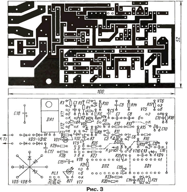
The switch is assembled on a printed circuit board made of one-sided foil-coated fiberglass laminate 1,5 mm thick, shown in Fig. 3. Diodes VD5-VD8 are installed one above the other to save space on the board.
Author: A.Rusin, Moscow
 See other articles Section Lighting.
Read and write useful comments on this article.
<< Back
 Latest news of science and technology, new electronics:
Air trap for insects
01.05.2024
Agriculture is one of the key sectors of the economy, and pest control is an integral part of this process. A team of scientists from the Indian Council of Agricultural Research-Central Potato Research Institute (ICAR-CPRI), Shimla, has come up with an innovative solution to this problem - a wind-powered insect air trap. This device addresses the shortcomings of traditional pest control methods by providing real-time insect population data. The trap is powered entirely by wind energy, making it an environmentally friendly solution that requires no power. Its unique design allows monitoring of both harmful and beneficial insects, providing a complete overview of the population in any agricultural area. “By assessing target pests at the right time, we can take necessary measures to control both pests and diseases,” says Kapil ... >>
The threat of space debris to the Earth's magnetic field
01.05.2024
More and more often we hear about an increase in the amount of space debris surrounding our planet. However, it is not only active satellites and spacecraft that contribute to this problem, but also debris from old missions. The growing number of satellites launched by companies like SpaceX creates not only opportunities for the development of the Internet, but also serious threats to space security. Experts are now turning their attention to the potential implications for the Earth's magnetic field. Dr. Jonathan McDowell of the Harvard-Smithsonian Center for Astrophysics emphasizes that companies are rapidly deploying satellite constellations, and the number of satellites could grow to 100 in the next decade. The rapid development of these cosmic armadas of satellites can lead to contamination of the Earth's plasma environment with dangerous debris and a threat to the stability of the magnetosphere. Metal debris from used rockets can disrupt the ionosphere and magnetosphere. Both of these systems play a key role in protecting the atmosphere and maintaining ... >>
Solidification of bulk substances
30.04.2024
There are quite a few mysteries in the world of science, and one of them is the strange behavior of bulk materials. They may behave like a solid but suddenly turn into a flowing liquid. This phenomenon has attracted the attention of many researchers, and we may finally be getting closer to solving this mystery. Imagine sand in an hourglass. It usually flows freely, but in some cases its particles begin to get stuck, turning from a liquid to a solid. This transition has important implications for many areas, from drug production to construction. Researchers from the USA have attempted to describe this phenomenon and come closer to understanding it. In the study, the scientists conducted simulations in the laboratory using data from bags of polystyrene beads. They found that the vibrations within these sets had specific frequencies, meaning that only certain types of vibrations could travel through the material. Received ... >>
| Random news from the Archive Biohybrid fish from human heart cells
17.02.2022
Researchers at Harvard University and Emory University (USA) have developed the first fully autonomous biohybrid fish from heart muscle cells derived from human stem cells. Artificial fish swims, recreating the muscle contractions of the heart, according to the press service of the Harvard School of Engineering and Applied Sciences. John A. Paulson.
The first self-contained biohybrid device is made from cardiomyocytes (heart muscle cells) derived from human stem cells. It mimics the shape and movements of the zebrafish. Unlike previous devices - a biohybrid jellyfish and an artificial ray made from rat heart cells - the biohybrid zebrafish has two layers of muscle cells, one on each side of the tail fin. When one side is compressed, the other is stretched. In response to the stretch, a protein channel opens, causing a contraction that triggers the stretch, and so on. A closed cycle is created, thanks to which the fish can move for more than 100 days.
The researchers have also developed a self-contained pacing unit, similar to a pacemaker, that controls the rate and rhythm of these spontaneous contractions. Together, the two layers of muscle and the autonomous stimulation node allowed for continuous, spontaneous and coordinated forward and backward movements of the fins.
Biohybrid fish only get better with age. The amplitude of muscle contractions, maximum swimming speed and muscle coordination increased during the first month as cardiomyocyte cells matured. Eventually, biohybrid fish achieved the same swimming speed and efficiency as zebrafish in the wild.
The development brings researchers closer to creating a more sophisticated artificial muscle pump and provides a model for studying heart conditions such as arrhythmia.
|
Other interesting news:
▪ Sunspots affect the climate
▪ Nanofilm that changes color
▪ Connecting with loved ones helps you live longer
▪ Skyrmions will increase the capacity of the hard drive by 20 times
▪ Getting electricity from blood sugar
News feed of science and technology, new electronics
 Interesting materials of the Free Technical Library:
▪ section of the site Normative documentation on labor protection. Article selection
▪ article Pilpe tongue to my larynx. Popular expression
▪ article What particles can rise from the core of the Sun to its surface for a million years? Detailed answer
▪ article Krupoveyshchik. Standard instruction on labor protection
▪ article Quartz-frequency meter. Encyclopedia of radio electronics and electrical engineering
▪ article Overhead power lines with voltage above 1 kV. General requirements. Encyclopedia of radio electronics and electrical engineering
Leave your comment on this article:
 All languages of this page
Home page | Library | Articles | Website map | Site Reviews

www.diagram.com.ua
2000-2024


 Arabic
 Bengali
 Chinese
 English
 French
 German
 Hebrew
 Hindi
Hindi Italian
 Japanese
 Korean
 Malay
Malay Polish
 Portuguese
 Spanish
 Turkish
 Ukrainian
 Vietnamese
