|
|


 Arabic
 Bengali
 Chinese
 English
 French
 German
 Hebrew
 Hindi
Hindi Italian
 Japanese
 Korean
 Malay
Malay Polish
 Portuguese
 Spanish
 Turkish
 Ukrainian
 Vietnamese
|
ENCYCLOPEDIA OF RADIO ELECTRONICS AND ELECTRICAL ENGINEERING The device for maintaining the microclimate in the winter garden is a home weather station. Encyclopedia of radio electronics and electrical engineering
Encyclopedia of radio electronics and electrical engineering / Power regulators, thermometers, heat stabilizers The proposed device is designed to maintain the microclimate in the winter garden, where subtropical plants are grown. With its help, the conditions necessary for their normal development are maintained: temperature, air humidity and daylight hours. Additionally, it can measure the external temperature and atmospheric pressure, accumulate and display in the form of graphs information about their changes during the year. The device provides automatic control of the water heating system of the room, air humidifiers, forced ventilation, electric drives of two window roller blinds, means of plant illumination. In fact, it implements some of the functions of the so-called "smart home" and can be used to control the microclimate in any room. At the same time, the device acts as a home weather station. It captures the outdoor temperature and atmospheric pressure (hourly), absolute minimums and maximums of outdoor temperature and atmospheric pressure for the current day, average daily values of outdoor temperature and atmospheric pressure during the current year, absolute minimums and maximums of outdoor temperature and atmospheric pressure for each quarter of the year with their dates. The indicator screen displays graphs of changes in meteorological parameters for the current day or for any past quarter of the current year. Main Specifications
The appearance of the device control panel is shown in fig. 1. It has two microcontrollers working together: ATmega32-16PU (main) and ATtiny2313A-PU (shade control). On fig. 2 shows the main part of its circuit diagram, which implements all functions, except for curtain control.
The real-time clock on the DD1 chip (DS1307) provides the DD2 microcontroller program with information about the current date and time. This microcircuit has 56 bytes of general-purpose RAM, which the DD2 microcontroller program uses to store information about daily changes in outdoor temperature and atmospheric pressure, as well as about the specified device parameters. For the DD1 chip, a backup power source is provided - a G1 CR2032 lithium cell, which allows you to save the clock and information in RAM in the absence of the main power supply. The element is installed in the "vertical" holder CH74-2032. Information about the state of the environment enters the DD2 microcontroller program from atmospheric pressure sensors B1 HP03M [1], temperature and humidity in the room B2 SHT10 [2], outdoor temperature BK1 DS18B20. Chip DD1 and sensor B1 are connected to microcontroller DD2 via interface I2C formed by lines SCL (PD4) and SDA (PD3). At the same time, for sensor B1, which works with three-volt logic levels, converters of these levels are provided. On the SCL and SDA lines, they are bidirectional (5 V↔1 V) on transistors VT2 (VT9) and resistors R17, R10 (R18, R5). MCLK and XCLR signal level converters are unidirectional (6 V→5 V) in the form of voltage dividers R1R2 and RXNUMXRXNUMX, respectively. The microcontroller communicates with the air temperature and humidity sensor B2 via lines PD1 and PD2. The outdoor air temperature sensor BK1 has a 1-Wire interface, the exchange with it is organized via the PD0 line of the microcontroller. To supply, if necessary, sound signals, a HA1 piezoceramic emitter is used, the control signal of which is generated by the microcontroller on the PD7 line. To display information, a graphic LCD WG240128B-TML-TZ#000 (HG1) with a screen resolution of 240x128 pixels was used. It is served by ports B and C of the microcontroller DD2. An essential advantage of this indicator is the built-in resistive touch panel, which greatly simplifies the implementation of controls. The panel is served by the PA0-PA3 lines of the DD2 microcontroller. To minimize the penetration of interference in the power circuit, it is fed to the analog nodes of the DD2 microcontroller through the L1C3 filter. The trimming resistor R24 sets the required contrast of the image on the LCD screen, and the selection of the resistor R21 sets the brightness of its backlight. Actuating devices are controlled using triac switches that provide galvanic isolation of their control circuits from the mains. These switches are identical, so we will consider the operation of only one of them. The control signal from the output PA5 of the microcontroller DD2 through the resistor R3 is fed to the emitting diode of the triac optocoupler U1 MOC3063. This optocoupler has a node for determining the moment when the voltage applied to the phototriac passes through zero, therefore, the opening of the phototriac and the power triac VS1 controlled by it occurs at this very moment. This ensures a minimum level of switching noise. To maintain the required lighting conditions in the room, the DD2 microcontroller program generates commands to control the position of the roller blinds. The part of the device circuit responsible for controlling the curtains is shown in fig. 3. There is a second microcontroller (DD3) here. The exchange of information between microcontrollers occurs along the lines RA6 and RA7 (DD2) and PD0, PD1 (DD3).
The curtain control unit allows using an electric drive to change the position of two roller blinds either automatically by commands generated by the DD2 microcontroller, or manually by the operator's commands. In this case, in automatic mode, the position of both curtains changes synchronously, and in manual mode, separate control of each of them is possible. In automatic mode, the step of moving the curtain is equal to half a turn of its shaft, in manual control mode, the user sets the desired position of the curtain using the buttons SB1-SB4. The electric drive of the left curtain consists of an electric motor M2, a sensor for the upper position of this curtain B3 and a sensor for the number of revolutions of its shaft B4. In the drive of the right curtain, the electric motor M1 and the sensors B5 and B6 are respectively installed. Sensors B3-B6 are magnetically sensitive microcircuits based on the Hall effect SS441A [3]. Permanent magnets are installed on the shafts and curtains to act on them. LEDs HL1-HL4 serve as indicators of the operation of the sensors, which greatly simplifies the establishment of the node. If desired, upon completion of the adjustment, these LEDs can be replaced with jumpers, and the resistance of the resistors R35-R38 can be increased so that the current flowing through each of them does not exceed 5 ... 10 mA. Gekko MR1-2 DC geared motors, widely used in robotics, are used as electric motors M25 and M275. The gearbox built into them with a gear ratio of 1:275 provides a torque on the output shaft of 330 Ncm, which allows you to raise and lower roller blinds with a curtain weight of up to 10 kg. The DD3 microcontroller controls the motors through the DA2 L298N dual-channel driver, issuing three control signals to it: the direction of rotation, generated on the PB6 line simultaneously for both curtains, and the permissions for each of the motors, generated on the OC1A and OC1B lines. The latter are sequences of pulses modulated in duration, which makes it possible to change the speed of movement of the curtains. The curtain control mode is set by switch SA1. In manual mode (switch open), the user controls the curtains using the buttons SB1 (right down), SB2 (right up), SB3 (left down) and SB4 (left up). In automatic mode (switch SA1 is closed), the buttons SB1-SB4 are blocked, and the commands to control the position of the curtains are received on the lines PD0 and PD1 of the microcontroller DD3 from the microcontroller DD2. Inductor L2 is designed to suppress interference penetrating into the power supply circuit of the device from running electric motors. It must be rated for a current of at least 2,5 A. The device is powered by a voltage of 5 V from a switching power supply PS-15-5 (5 V, 2,8 A). The current consumption from it (when the curtain drive motors are off) is about 90 mA. The voltage of 1 V required to power the sensor B3,3 is obtained using the integral stabilizer DA1 L78L33. A drawing of the main printed circuit board of the device is shown in fig. 4. The placement of parts on it is shown in fig. 5. For microcontrollers DD2 and DD3, panels are installed on the board due to the fact that there are no connectors for programming microcontrollers on it. Pins 2 and 12 have been removed from the DD13 microcontroller panel.
To install the HP03M (B1) sensor on the board, pieces of tinned single-core wire with a diameter of 0,4 ... its contact areas. For the SHT0,8 (B6) sensor, it is advisable to make a small adapter printed circuit board according to the drawing shown in fig. 10.
Chip L298N (DA2) should be provided with a small heat sink with a cooling surface area of 20...30 cm2. Heat sinks for triacs VS1-VS4 are not provided, therefore the power switched by them should not exceed 200 VA. To work on a more powerful load, triacs must have appropriate heat sinks. The device is assembled in a standard electrical box. Outside the main board there are sensors B2-B6, as well as a 5 V supply voltage. The HG1 indicator, the SA1 switch and the SB1-SB4 buttons are located on the removable front panel of the case and are connected to the main board with connectors. Please note that the indicator's touch panel leads are in the form of an ultra-flat FPC cable designed to connect to the FFC connector. Since the indicator is located on the removable panel of the housing, the length of this cable (8 cm) is not enough to connect to the board. It is connected to it through an extension cable - a flat cable 10 cm long, the wires of which are soldered to the pins of the FFC connector on one side, and on the other, a BLS-4 connector is installed for connecting to the printed circuit board. Magnetic sensors B3-B6 are installed in pairs on two identical printed circuit boards, made according to the drawing shown in fig. 8. These boards are located near the curtains and are connected by cables to connectors X15 and X16 of the main board. Actuators are connected to connectors X4, X5, X10, X11, X13, X14. The 5V voltage supply is a separate node located on its own printed circuit board.
Design features of actuators Illumination of plants can be carried out both with special phytolamps and conventional ones designed to illuminate the room, if the intensity and spectrum of their radiation are suitable for plants. In the latter case, it is necessary to carefully consider the scheme for switching on lamps so that it does not happen that the same wire of the lamp is connected by its wall switch to the phase wire of the network, and through the X4 connector to the neutral wire, which will lead to an accident. To ensure the required air humidity in the room, household humidifiers can be used (one or more, depending on the area of the room). The humidifier should be as simple as possible, with no built-in humidity controls. The switch on the humidifier body must be constantly on, the mains cord is connected to the X5 connector. The device will automatically turn the humidifier on and off. To control water heating, a Danfoss RAV8 valve with a normally open thermoelectric actuator Danfoss TWA-V NO 230 V is installed in the break of the pipe supplying hot water to the system. The drive supply voltage is 230 V, power consumption is only 1 W. Due to the fact that the valve is normally open, if there is no control voltage on the drive, the heating system will be turned on. This will prevent freezing of plants in winter as a result of a malfunction of the device or a lack of voltage in the mains. The room ventilation system may contain both supply and exhaust fans or a combination of both. The total power of the fans must not exceed 200 VA. The author used curtains made on the basis of window roller blinds with a manual chain drive (Fig. 9). They are produced in different sizes and with different colors of the canvas and are sold in many stores. Since the main task of curtains in a summer garden is to reduce the influx of heat into the room by shielding solar radiation, it is advisable to choose them with a light (well-reflecting light), but at the same time dense (with low light transmission) canvas. In this case, the curtains will be most effective. The width of the curtain is chosen based on the complete overlap of the window opening, and the length is 40 ... 50 cm more than the height of the window.
The curtain consists of a metal shaft with a diameter of 25 mm, on which the curtain fabric is wound. Plastic bushings are inserted into the shaft holes on both sides, the axes of which freely rotate in the holes of the brackets, with the help of which the entire structure is attached to the wall. On the right sleeve there is a curtain drive mechanism, which allows you to raise and lower its canvas using a ball chain. To supply the curtain with an electric drive, this sleeve must be modified. The cover fixed with latches is removed from it, after which the ball chain is removed from the pulley. A metal shaft with elements of the brake system is removed from the outer end of the bushing, with the help of which it is fixed in the bracket hole. The brake system does not allow the canvas to unwind under its own weight. In a curtain with an electric drive, the brake function is performed by the electric motor reducer, which, due to the large gear ratio, creates a significant braking torque when transferring force in the direction from the curtain to the motor. Gekko MR25-275 geared motors are sold in robotics stores. Adapter bushings were also purchased there for connecting the shafts of motor-reducers with the mechanisms driven by them, as well as cylindrical magnets with a diameter of 3 and a height of 3 mm and rectangular magnets with dimensions from 10x10 to 20x20 mm with a thickness of 3 ... 4 mm. From metal corners 40x60 mm 40 mm long with a shelf thickness of 2,5 mm, brackets were made for mounting the motor-reducers to the wall. The sleeve with the pulley for the drive chain removed from the curtain had to be modified according to fig. 10. In its outer end, two holes with M3 threads are drilled for countersunk screws, which secure the adapter sleeve for the motor-reducer shaft. In the groove of the pulley, in which the ball chain was previously located, two holes were drilled diametrically opposite with a diameter of 3,5 and a depth of 6 mm.
Pairs of bar magnets 3 mm long were used to make magnets 3 mm in diameter and 6 mm long. Each pair of rods is connected by opposite poles, and a piece of a heat-shrinkable tube with a diameter of 3 mm is put on and slightly warmed up. Unfortunately, it was not possible to find ready-made magnets of the required size, so I had to assemble each of the two smaller ones. The resulting magnets are glued into the holes of the pulley flush with its outer surface. When the curtain shaft rotates, they must act on the magnetic sensor of its half-turns. A bracket for mounting the motor-reducer to the wall is made of a metal corner. Holes for the motor-reducer shaft and its fixing screws must be drilled on the corner shelf. The hole for the shaft should be the same distance from the surface of the wall bracket as the factory bracket at the opposite end of the shaft. Two holes are drilled in the sole of the corner for its fastening to the wall. They should be located away from the longitudinal axis of the gearmotor, otherwise it may be difficult to install the bracket on the wall. The curtain should be fixed to the wall approximately 15 cm above the top of the window opening. It is advisable to do this in the following sequence: - fix the motor-reducer on the bracket made for it; - install the right and left (modified) bushings in the holes of the curtain shaft. It should be borne in mind that the curtain fabric must be wound on the shaft from the side of the wall and window; - assemble the curtain on a horizontal surface (for example, on the floor), inserting the shaft of the right sleeve into the hole of the factory bracket, and the shaft of the motor-reducer into the central hole of the adapter sleeve installed on the modified left sleeve, and fix it with the screw in the adapter sleeve; - measure the distances between the holes for fixing the brackets to the wall; - according to the results of measurements, mark holes on the wall, drill them and insert dowels into the holes; - remove the right bracket from the assembled structure and fix it on the wall using the prepared holes; - carefully lift the remaining part of the assembled curtain, insert the shaft of the right sleeve into the hole of the bracket installed on the wall; - fasten the bracket with the geared motor to the wall using the prepared holes. The view of the installed curtain from the side of the electric drive is shown in fig. 11. Now you can apply a constant voltage of 5 V to the motor-reducer in different polarity and check the movement of the curtain leaf in both directions.
Install the printed circuit board with magnetic sensors on the wall under the curtain shaft, as shown in fig. 12. Shaft speed sensor (B4 or B6) must be located under the pulley with magnets. The minimum distance from the magnet to the sensor body must be 3...5 mm. After applying power to the board, turn the shade shaft. If the passage of each magnet over the sensor is accompanied by a flash of the LED, everything is fine. Otherwise, you should reduce the distance from the magnet to the sensor by bending its leads.
Next, adjust the curtain up position sensor. To do this, bring the curtain fabric to a position that will be considered the top. Usually it corresponds to a fully open window opening. Place a rectangular magnet opposite the sensor on the curtain fabric from the side of the wall. On fig. 11 you can see a ring magnet (any other will do), holding a rectangular one on the canvas during the adjustment process. The bright spot above it is an LED shining through the canvas. If the LED does not turn on, by bending the sensor leads, reduce the distance between it and the magnet. Then lower the curtain leaf until the LED turns off and raise it again until it turns on. If the position of the curtain at the moment the LED is turned on does not coincide with the required upper position, the position of the magnet on the curtain should be corrected. Upon completion of the adjustment, glue the magnet to the canvas in the found place with Moment glue. The last action is counting the number of half-turns of the curtain shaft, during which its canvas will move from the upper (open) to the lower (closed) position. It depends on the height of the window, and its values in each case may vary. The technique here is simple - counting the number of LED flashes in the process of closing the curtains. Remember this number, in the future it will need to be entered into the microcontroller program. After that, the motor-reducer and the sensor board can be connected to the main board of the device. General information about the algorithms of the device For the normal development of subtropical plants, a day length of approximately 12 hours is required. However, in many regions of our country, during a significant part of the year, it is much shorter. For example, at the latitude of Moscow, its minimum duration is about 7 hours. To control the illumination of plants, at the beginning of each day, the device calculates the time of sunrise Tw and sunset Tz at the point of its location (the latitude and longitude of this point are recorded in the program) and, based on this information, calculates the current length of daylight Tsv. The program also stores the user-specified value of the required daylight hours Tsv.tr. If Тsv < Тsv.tr, then the difference between them is calculated: Δ = Тsv.tr - Тsv. This is the amount of time by which the current length of daylight should be increased. In the morning, the device turns on the backlight Δ/2 before sunrise and turns it off at sunrise. In the evening, it turns on the backlight at sunset and turns it off ∆/2 after sunset. An algorithm for calculating sunrise and sunset was used, based on the one given in [4]. The user sets the required humidity in the room using the menu within the range of 40 ... 70%. If the humidity is less than required by 5%, the device turns on the humidifier and turns it off when the set value is reached. For the normal development of plants in the room, a certain temperature must be maintained. At the same time, it is impossible to maintain a constant temperature in it throughout the year - plants also have a "concept" about the seasons, and each season must have its own average air temperature corresponding to the subtropical climate. To fulfill this requirement, the EEPROM of the DD2 microcontroller contains the law of temperature changes in the room by months during the year. It contains the values of comfortable and minimum allowable temperature for each month according to table. 1. Table 1
By controlling the operation of the heating system, ventilation and window curtains, the device seeks to maintain the temperature in the room that differs from the comfortable one by no more than 1 оC. In practice, however, this tolerance can only be maintained in the cold season, when the common house heating system is in operation. The rest of the time, when there is an excess heat influx into the room, the device seeks to prevent the comfortable temperature from exceeding. If the room temperature falls below the minimum allowable temperature for any reason, the device emits a series of three short beeps approximately once a minute. The exchange of information between the two microcontrollers occurs along the lines connecting pin 34 (PA6) DD2 with pin 2 (PD0) DD3 and pin 33 (PA7) DD2 with pin 3 (PD1) DD3. The microcontroller DD2 is the master, and DD3 is the slave. In the initial state, the outputs PA7 and PA6 of the master are configured as inputs, and the lines PD1 and PD0 of the slave can be in one of the states shown in table. 2. In the slave's ready to receive state, PD1 and PD0 are configured as inputs, and the logic-one levels on them are supported by resistors R30 and R31. Table 2
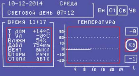
If the slave is in the ready state, the master can generate a request to read the current position of the shades or a command to change the position of the shades. In both cases, one byte is transferred. When answering a request, this byte encodes the current position of the curtain - how many half-turns, counting from the top position, it is lowered. In the byte of the command to change the position of the curtains, the most significant bit of the byte indicates the direction of movement (1 - lower, 0 - raise), and the rest - the number of half-turns of movement. When issuing a request to read the position of the curtains, the host configures its PA7 and PA6 pins as outputs and sets code 20 on them for 01 ms. After that, it reconfigures the pins to the input mode (with the logical one levels on the lines holding the resistors R30 and R31) and waits bytes of information from the slave. The slave, after waiting for the PD0 pin to return to a single state, configures its PD1 and PD0 pins as outputs and starts transmitting. It transmits information in a serial code on the PD0 line, accompanying each bit with a clock pulse on the PD1 line. Upon completion of the transfer, the slave configures its PD1 and PD0 pins as inputs. To send a command to change the position of the curtains, the host configures the PA7 and PA6 pins as outputs and sets the code 20 on them for 00 ms, after which it starts transmitting the command byte, generating its serial code on the PA6 pin and accompanying each bit with a clock pulse on the PA7 pin. Upon completion of the transfer, the master configures its PA7 and PA6 pins as inputs. The slave, having received the code combination 00, switches to the command reception mode. Having completed the reception, it configures its outputs PD1 and PD0 as outputs, sets code 10 ("Not ready to receive") on them, and proceeds to execute the command, having previously checked its contents for validity. If an invalid value is found in the command during validation, it will be replaced with one that is within acceptable limits. After executing the command, the slave returns to the ready state. The operation algorithm of the DD2 microcontroller in a simplified form can be represented as consisting of nested cycles: annual, daily, hourly, temperature control and the main one. At the beginning of the next year, the correctness of its change is checked. The fact is that the value in the year register can change not only as a result of its natural change, but also for a number of other reasons. For example, if the real-time clock chip fails or malfunctions. An untimely "New Year" threatens that the weather data accumulated in EEPROM for all the time that has passed since the beginning of the current year will be destroyed. Checking the correctness of the year change is considered successful if the current year is one more than the previous one. To be able to check this, during the date setting process, the year value is loaded both into the register of the real-time clock chip and into the EEPROM of the microcontroller, from where it is selected as a control during the test. If the test is successful, the program updates the year reference value in the EEPROM and erases last year's weather data. Otherwise, the content of EEPROM remains unchanged, and instead of the name of the day of the week, the program displays the message "YEAR ERROR" on the indicator and continues to work. At the beginning of each day, the program calculates the values of the outside air temperature and atmospheric pressure averaged over the past day. This information is entered into the next cells of the EEPROM area that stores weather data for the current year. It is checked whether the maximum and minimum values for the current quarter outside temperature and atmospheric pressure need to be updated. If required, the values stored in the EEPROM will be updated. The RAM cells of the real-time clock are reset, storing information about the daily course of the outdoor temperature and atmospheric pressure. Information about the permissible room temperature is read from the EEPROM. Then, the moments of sunrise and sunset, the current duration of daylight hours, the moments of turning on and off the means of supplementary lighting of plants are calculated. When the next hour comes, the program enters the values of the outside temperature and atmospheric pressure measured at the end of the previous hour into the RAM cells of the real-time clock. It updates the graphs of the daily course of temperature and atmospheric pressure. In the temperature control cycle, the program controls the operation of heating systems, ventilation and the position of window shades. The initial data for regulation are the temperature in the room, its gradient, the state and availability for control of heating and ventilation systems, as well as window blinds. In contrast to the cycles considered above, which are executed by the program with a constant frequency, the user can change the period of repetition of the control cycle in the range from 2 to 30 minutes. The fact is that the change in temperature in the room under the influence of means of its regulation does not occur instantly, but with some delay, depending on a number of factors, for example, on the heat capacity of the room and the effectiveness of the means of regulation. Therefore, in each specific case, the optimal period for the implementation of this cycle must be selected experimentally. And finally, the main loop, which the program repeats with a period of about a second. In this cycle, it reads and displays information from temperature, humidity, pressure sensors and from a real-time clock, controls the humidifier, turns on and off the illumination of plants, polls the controls. When the appropriate conditions are met, the cycles discussed above are called from the main loop. The program of the microcontroller DD3 when it is turned on, first of all, raises the curtains to the top position. It is believed that their position was arbitrary and unknown to the program, and for correct control it must have a reference point, which is the upper position of the curtains. The same action is performed when switching the curtain control system from manual to automatic mode, since in this case the program considers the current position of the curtains unknown. In the manual control mode, the program sets the code 2 (a sign of manual control) on the communication lines with the DD00 microcontroller and then constantly checks the status of the SB1-SB4 buttons. Depending on it, it generates control signals for curtain motor drives. When the curtains move, the program controls the state of the sensors of their upper position. If the curtain rises, the sensor will block its further rise. But when the curtain is lowered, there is no software control of its position (it cannot be reliably organized with the existing set of sensors), so the user exercises this control visually, stopping the curtain at the right time. In automatic control mode, the software configures PD0 and PD1 pins as inputs and constantly checks their status. When a request from the host is detected, the program identifies its type and either transmits information about the current position of the curtains, or receives a command to change their position. If the received command requires to lower the curtain, then first of all it is checked for admissibility. The meaning of the check is to prevent the canvas from lowering below the permissible level - as noted above, there are no sensors for the lower position of the curtains in the device. The verification algorithm is simple - the current position of the curtain (the number of half-turns of the shaft from the top position) is summed up by the program with the number of half-turns contained in the command. If the result exceeds the maximum allowed value stored in the program, then the accepted value is limited. When the curtains are raised, no check is necessary, as in any case it will be stopped by the signal from the upper position sensor. The program provides for the obligatory lifting of curtains after sunset, since at night they do not perform heat-shielding functions. Information displayed on the indicator When turned on, the device operates in the basic information display mode (Fig. 13). The indicator displays the current date, time and day of the week, daylight hours for the current day, atmospheric pressure, indoor and outdoor temperature, indoor humidity. User-set heating, ventilation and curtain control modes are shown.
At the top right, the current state of the controlled devices is displayed: "Vn" - ventilation, "From" - heating, "Sv" - means of plant illumination, "Uv" - air humidifier. If the device is currently turned on, its designation is surrounded by a frame. On fig. 13 - this is heating and lighting of plants. In the lower right part of the screen, a graph of the daily course of the outside temperature or atmospheric pressure (at the user's choice) is displayed. To the right of the graph, in rectangular frames, the maximum (top) and minimum (bottom) values of the parameter displayed on the graph for the past part of the day are placed. Three areas of the screen serve as touch control buttons. On fig. 13 they are surrounded by red frames (there are no such frames on the screen). By pressing the middle button, you can select the parameter displayed on the graph (atmospheric pressure or outside temperature), and by pressing the right button, you can switch the indicator to the mode of displaying meteorological data accumulated over the past part of the current year. The screen view of the indicator in this mode is shown in fig. 14. Since the screen resolution is not sufficient to display information for the whole year, it is displayed quarterly. In the upper part of the screen, the number of the quarter (in a frame) and the values of the absolute maximums and minimums of the outside temperature and atmospheric pressure for the selected quarter are displayed, indicating the dates on which they were recorded.
In the middle part of the screen there is a graph of changes in daily average values of outdoor temperature and atmospheric pressure during the quarter. The pressure curve is shown as a thick line, and the temperature curve as a thin line. By default, entering this mode displays data for the current quarter. You can go to other quarters using the on-screen buttons "PREV" and "NEXT", and by pressing the on-screen button "EXIT" you return to the mode of displaying the main information. If there is no data for the selected quarter in the device's memory, the message "NO DATA" will be displayed. Service menu Use this menu to set the values of the parameters used in the operation of the device. It allows you to set: - current date, time and day of the week; - time zone of the location of the device in hours relative to UTC. This information is needed to calculate the time of sunrise and sunset; - the required duration of daylight hours in the range of 10 ... 20 hours with a resolution of 1 hour; - the required air humidity in the room in the range of 40 ... 70% with a resolution of 1%; - mode of using the heating system "Manual" or "Automatic". In the "Automatic" mode, the heating system works according to the program, in the "Manual" mode there is no control, the thermoelectric drive is de-energized, and the control valve is open. Room heating radiators are permanently connected to the general house heating system. It is advisable to turn on this mode in the summer, when heating is not required; - mode of using the ventilation system "Off" or "Automatic"; - the period of repetition of the temperature control cycle within 2 ... 30 minutes with a discreteness of 1 minute. In addition, the menu provides the possibility to erase the information about the daily course of the outside temperature and atmospheric pressure from the memory. This operation should be performed when the device is turned on for the first time, as well as after changing the backup battery of the real-time clock chip. Otherwise, the RAM cells of this microcircuit will contain random values that have nothing to do with real values, on the basis of which the program will build a daily schedule. Even worse, these unpredictable values will be included in the annual statistics. Enter the menu by pressing the left screen button (see Fig. 13). The indicator screen will take the form shown in fig. 15. The name of the parameter and its current value will be displayed in the frame. There are on-screen buttons for selecting the "PREV" and "NEXT" parameters, changing the current parameter "+" and "-", as well as exiting the menu while saving the "EXIT" parameters. You can exit the menu at any time, it is not necessary to go through all the parameters, it is enough to correct only the necessary ones.
Features of preparing programs for microcontrollers Due to the lack of program memory of the DD2 microcontroller, it was not possible to implement all the service functions of the device through the menu. In other words, some parameters have to be specified in the program text before compiling it. True, there are only three such parameters, and they do not need to be changed during the use of the device. These are the geographic coordinates (latitude and longitude) of the place where the device is used, as well as the number of pulses of the curtain shaft half-turn sensor required to move its curtain from the uppermost to the lowermost position. The last number must also be entered into the DD3 microcontroller program. For this reason, the boot (.hex) program files attached by the author to the article can be fully used only if the device is located at a distance of no more than 70 ... 100 km from Moscow (its coordinates are indicated in the program), and window curtains fall down for 25 half-turns of the shaft. In other cases, the texts of the programs need to be corrected. To do this, at the beginning of the source code of the DD2 microcontroller program (file klimat_mega.bas), find the lines after the declaration of variables: La = 55.5 'Latitude (deg.) Lo = 37.5' Longitude (degrees) Stepmax=25 'Number of steps and replace the values of the variables in them with the ones you need. At the beginning of the source text of the DD3 microcontroller program (file klimat_tiny.bas), find the line Stepmax = 25 'Number of steps and replace the number 25 in it with the number of steps (half-turns) for your curtain. After that, compile both programs and upload the codes from the resulting hex files to the microcontrollers. The order of programming microcontrollers Programming the microcontroller DD2 (ATmega32-16PU) should be performed in the following sequence: 1. Program the microcontroller configuration in accordance with the table. 3. 2. Load the codes from the Init_Mega.hex file into the microcontroller and run this program. It will prepare the EEPROM of the microcontroller for operation - it will load information from the table into it. 1 and clear the area where the weather data for the year is placed (if the microcontroller has already been used, there may be information recorded by previous programs). 3. After five to ten seconds, download the compiled work program to the microcontroller. Programming the DD3 microcontroller has no special features. Its configuration must correspond to the table. 4. Table 3
Table 4
PCB files and microcontroller programs can be downloaded from ftp://ftp.radio.ru/pub/2016/09/clim.zip. Literature
Author: A. Savchenko
Machine for thinning flowers in gardens
02.05.2024 Advanced Infrared Microscope
02.05.2024 Air trap for insects
01.05.2024
▪ PT8 Neo - motherboard based on VIA FSB800 chipset from MSI ▪ Electronic Notebook Sharp WG-PN1 ▪ There are fewer bees, but crops have not fallen ▪ Highly efficient electrocatalyst for clean energy
▪ section of the website Audiotechnics. Article selection ▪ Article Dreaming Dreams. Popular expression ▪ article What is a dolphin? Detailed answer ▪ Motonart article. Personal transport ▪ article Starter car. Encyclopedia of radio electronics and electrical engineering
Comments on the article: Alexander Someone repeated the device?
Home page | Library | Articles | Website map | Site Reviews
www.diagram.com.ua | ||||||||||||||||||||||||||||||||||||||||||||||||||||||||||||||||||||||||||||||||||||||||||||||||||||||||||||||||||||||||||||||||||||||||


 Leave your comment on this article: