|
|


 Arabic
 Bengali
 Chinese
 English
 French
 German
 Hebrew
 Hindi
Hindi Italian
 Japanese
 Korean
 Malay
Malay Polish
 Portuguese
 Spanish
 Turkish
 Ukrainian
 Vietnamese
|
ENCYCLOPEDIA OF RADIO ELECTRONICS AND ELECTRICAL ENGINEERING Automatic switch of household radio equipment. Encyclopedia of radio electronics and electrical engineering
Encyclopedia of radio electronics and electrical engineering / Clocks, timers, relays, load switches Most modern household radio equipment is controlled remotely using IR remotes, smartphones, etc. At the same time, it does not completely disconnect from the network, but goes into the so-called standby mode with the main functions turned off and low power consumption. This mode has its advantages and disadvantages. The main convenience is the constant readiness to work with the remote control. The disadvantages include additional power consumption, which is sometimes significant, as well as a permanent connection to the network, which does not increase the reliability of the radio equipment. The proposed device completely disables the equipment. The principle of its operation is based on the fact that the current consumed by the load in operating and standby modes differs several times. The scheme of the device is shown in fig. 1. Electronic keys are assembled on transistors VT1, VT4, diode VD3 is a half-wave rectifier, resistor R3 is a load current sensor. Diodes VD1, VD2 limit the voltage on the sensor. After connecting to the network through the diode VD3 and resistor R4, capacitor C1 begins to charge, and through the same diode and resistor R5, capacitor C2 begins to charge. The capacitance of capacitor C2 is smaller, so it charges faster, and the opening voltage, limited by the Zener diode VD5, is supplied to the gates of transistors VT1 and VT4. They open, and as a result, mains voltage is applied to the load.
If the load is in standby mode, the current consumed by it is small, the transistor VT2 does not open, so the charging of the capacitor C1 continues. Until it is charged (several tens of seconds), it is necessary to transfer the load to the operating mode, otherwise the device will de-energize it. Part of the mains voltage drops across resistor R3 and diodes VD1, VD2, as well as transistors VT1, VT4. But this drop is small and does not exceed 2...3 V. If the load is in operating mode, the voltage across the resistor R3 is sufficient to open the transistor VT2, which discharges the capacitor C1, so the transistor VT3 is closed. A current-limiting resistor R2 is included in the base circuit of the transistor VT2. Since the starting current of the connected load is usually unknown, a resistor R1 is introduced to limit it. If you transfer the load to standby mode, the current consumption will decrease significantly and the voltage across the resistor R3 will no longer be enough to open the transistor VT2, so the capacitor C1 will start charging and the transistor VT3 will open. As a result, the capacitor C2 will quickly discharge, the transistors VT1, VT4 will close, the load will be de-energized. Diode VD4 limits the voltage at the gate of the transistor VT3 at 13 ... 14 V. To turn on the device, briefly press the button SB1. In this case, the capacitor C1 is discharged, C2 is charged, transistors VT1, VT4 open and the mains voltage is supplied to the load. The selection of the resistor R3 is carried out experimentally, taking into account the fact that the opening voltage of the transistor VT2 is 0,5 ... turned it off. The need for an experimental selection is due to the fact that modern radio equipment mainly uses switching power supplies, which rarely contain a built-in power factor corrector, and the current consumed is of a pulsed nature. Therefore, the amplitude of the consumed current can be several times greater than its average value. All elements, except for the XP1 plug and the XS1 socket, are mounted on a printed circuit board made of 1,5 ... 2 mm thick foil fiberglass on one side, the drawing of which is shown in fig. 2. The device uses resistors P1-4, S2-23, MLT and powerful imported, oxide capacitors - imported, diodes VD1, VD2 - any of the 1N400X series, diode VD3 - low-power rectifier with a permissible reverse voltage of at least 400 V, VD4 - any low-power rectifier or pulse. The zener diode is low-power, optionally two-anode, for a stabilization voltage of 8 ... 12 V. IRF840 transistors can be replaced with IRFBC40 transistors. Replacing the KT342BM transistor - any of the KT3102 series. Button - clock small with self-return.
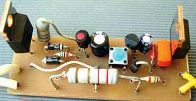
The appearance of the mounted board is shown in fig. 3. It is placed in a plastic case of suitable dimensions. A socket for connecting the load is installed on the wall of the case, the button is provided with a plastic pusher, and a hole is made for it in the case.
The maximum load current should not exceed 1 ... 1,5 A, since it is limited by the allowable current of the diodes VD1, VD2 and the absence of heat sinks for transistors VT1 and VT4. To increase the current by 2 ... 3 times, these transistors should be equipped with heat sinks with an area of 10 ... 12 cm2 and replace the diodes VD1, VD2 with more powerful ones. Author: I. Nechaev
Machine for thinning flowers in gardens
02.05.2024 Advanced Infrared Microscope
02.05.2024 Air trap for insects
01.05.2024
▪ Dust-resistant, waterproof lenses Canon Dust Donuts ▪ 23" Full HD Philips display with ErgoSensor technology ▪ Laser space communications will be tested from the moon
▪ section of the site Note to the student. Article selection ▪ article by Irvine Shaw. Famous aphorisms ▪ article How was the planet Pluto discovered? Detailed answer ▪ Tetraclinis article. Legends, cultivation, methods of application ▪ Article Phasometer. Encyclopedia of radio electronics and electrical engineering ▪ article Cutting the finger. Focus Secret
Home page | Library | Articles | Website map | Site Reviews
www.diagram.com.ua |


 Leave your comment on this article: