|
|


 Arabic
 Bengali
 Chinese
 English
 French
 German
 Hebrew
 Hindi
Hindi Italian
 Japanese
 Korean
 Malay
Malay Polish
 Portuguese
 Spanish
 Turkish
 Ukrainian
 Vietnamese
|
ENCYCLOPEDIA OF RADIO ELECTRONICS AND ELECTRICAL ENGINEERING Electrostatic filter in a vacuum cleaner. Encyclopedia of radio electronics and electrical engineering
Encyclopedia of radio electronics and electrical engineering / Home, household, hobby Household vacuum cleaner filters do not trap dust particles with a diameter of less than one micrometer. During the cleaning of the premises, this dust, swirling in the stream of air coming out of the vacuum cleaner, is inhaled by the person and deposited in his lungs. However, dust can be deposited even inside the vacuum cleaner, taking advantage of its property to be attracted to surfaces under high electrical potential. To do this, it is enough to place a fine metal mesh in the path of the air flow in the vacuum cleaner and apply a high negative voltage to it.
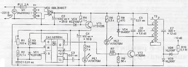
The source of such a voltage can be built according to the circuit shown in Fig. 1. Powered by a network of 220 V, 50 Hz, it creates an output voltage of at least -10 kV at a load current of about 3 μA. The DA1 timer chip is a generator of rectangular pulses, the frequency of which can be changed by a tuning resistor R1 from one to several kilohertz. In practice, by changing this frequency, the output high voltage is regulated, achieving maximum filter efficiency. A timer supply voltage regulator is built on the VT1 transistor and the VD3 zener diode. The pulses from the output of the timer amplify the transistor VT2, which has a high current transfer coefficient. Its collector circuit includes the primary winding of the T2 transformer - the output line from the portable black-and-white TV "Youth". Elements C5, C6, R8, VD4 - damping circuit. It eliminates self-induction voltage surges dangerous for the transistor on this winding. Capacitor 07 and diodes VD5, VD6 form a high-voltage rectifier. Its smoothing filter consists of a resistor R10 and its own capacitance installed in the vacuum cleaner mesh. In addition, the resistor R10 limits the current during spark discharges between the mesh and parts of the vacuum cleaner, as well as when accidentally touching it with your hand.
The power supply unit of the high voltage source is built on a step-down transformer T1 and a diode assembly VD2. Capacitor 02 smoothes the rectified voltage, and the HL2 LED indicates its presence. The printed circuit board of the source is shown in fig. 2. It can be easily placed in the body of almost any vacuum cleaner. The tuning resistor R1 is installed separately in a place accessible for adjustment. Separately placed and transformer T1. Transistor VT2 is equipped with a heat sink measuring 30x15x10 mm. The parts of the high-voltage rectifier are mounted near the transformer 12 in a hinged way on insulating racks. Their height and distances between mounting points must be sufficient to prevent breakdowns both between parts under high voltage and between them and other elements of the source - at least 10 ... 15 mm. Capacitor C7 is soldered directly to terminal 7 of transformer T2, located at the top of its coil. The high voltage output is made with a high-voltage wire used in TVs. In order for the electric charge accumulated in high-voltage elements to “dissolve”, all work on establishing the described source, cleaning or repairing the vacuum cleaner in which it is installed, should be carried out no earlier than 3 ... 5 minutes after disconnecting from the mains. Capacitor C6 - K15-5, 07 is imported, it can be replaced by the domestic K73-14 series with a capacity of 470 pF at 16 kV. The rest of the capacitors are conventional ceramic and oxide. The SBL2040CT diode assembly can be replaced with two separate KD213B diodes. Instead of the KT3102B transistor, you can install KT312B, and instead of KT829A - imported BDX53C. Transformer T1 must have two secondary windings of 12 V each with a permissible load current of 1 ... 1,5 A. The author used a transformer TN36-220-50, connecting in series four of its windings of 6,3 V. The assembled source is connected to the network at the middle position of the trimmer resistor R1. If there are no faults, both LEDs should light up. Bringing a neon lamp (for example, TN-7) to terminal 2 of the T0,2 transformer (but not touching it), observe its glow and, by rotating the tuning resistor, achieve its maximum intensity. To increase or decrease the output voltage, you can transfer the wire coming from the rectifier on the VD2 diode assembly from terminal 2 of the transformer T2, respectively, to terminal 3 or 1. After a preliminary check of the source outside the vacuum cleaner, it is installed in place and connected to a metal mesh placed in front of the inlet of the vacuum cleaner fan. It is advisable to apply voltage to the primary winding of the transformer T1 from the terminals of the electric motor of the vacuum cleaner so that the filter starts working simultaneously with it. Since a large amount of dust sticks to the filter mesh, it must be cleaned periodically, remembering to first disconnect the vacuum cleaner from the mains and wait a few minutes for the electric charges to drain. Source PCB file in Sprint Layout 5.0 format can be downloaded hence. Author: V. Konovalov, Irkutsk; Publication: radioradar.net
Artificial leather for touch emulation
15.04.2024 Petgugu Global cat litter
15.04.2024 The attractiveness of caring men
14.04.2024
▪ Fujitsu Raku Raku - a smartphone for pensioners ▪ Professions disappearing and promising ▪ Collagen fibers grow like a sunflower
▪ section of the site Consumer Electronics. Selection of articles ▪ article Extraction from water. Occupational Safety and Health ▪ article Which company recycles old sneakers into material for new sports fields? Detailed answer ▪ Dashin article. Legends, cultivation, methods of application ▪ article Automatic starter-charger. Encyclopedia of radio electronics and electrical engineering
Home page | Library | Articles | Website map | Site Reviews
www.diagram.com.ua |


 Leave your comment on this article: