Improved GIR. Encyclopedia of radio electronics and electrical engineering

Encyclopedia of radio electronics and electrical engineering / Measuring technology
 Comments on the article
Everyone who has dealt with a heterodyne resonance indicator knows that working with it is a rather painstaking task, because. during the measurement process, it is necessary to manipulate not only the frequency adjustment knob, but also the sensitivity control of the device, and in some designs [1] also the mode knob.
This is due to the fact that in almost all oscillators tunable in a wide frequency range [1, 2], the RF voltage amplitude also varies over a wide range. In order not to miss the moment of resonance, the tuning knob must be rotated as slowly as possible and carefully observe the readings of the dial indicator.
Working with the GIR is greatly simplified and accelerated if it is supplemented with a device that fixes the moment of resonance with some kind of light indicator.
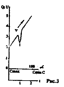
On fig. 1 shows a diagram of a GIR with an LED resonance indicator. Its operation is illustrated by the graphs in Fig. 2 and fig. 3. The higher the rotation speed of the tuning capacitor rotor, the steeper the front of the change in the RF voltage on the circuit (line A1 in the graphs of Fig. 2 and Fig. 3).
The task is to fix a sharp decrease in the level of HF voltage. It is solved by using a differential amplifier, which, in the general case, does not respond to the absolute value of the parameter, but to its change in any direction.
The GIR master oscillator is assembled on a transistor VT1 according to the scheme described in [3]. The differential amplifier is assembled on transistors VT3, VT4, VT5. When tuning in the range in the direction of decreasing capacitance or, which is the same, in the direction of increasing the RF voltage (shown by the arrow in Fig. 2 and Fig. 3), the rectified voltage of negative polarity at the VT3 gate increases smoothly.

On the drain VT3 and the left plate of the capacitor C7, the positive polarity voltage also increases smoothly. Transistors VT4 and VT5 are locked. At the moment of resonance, the voltage at the VT3 gate changes sharply towards a positive potential, there is a sharp drop in the drain potential of VT3. Capacitor C7 "transfers" this potential drop to the base VT4. As a result, VT4 and VT5 open and the HL1 LED flashes brightly. Flash duration depends on the C7R7 charge time constant.
On the transistor VT2, a DC amplifier for the measuring device is assembled
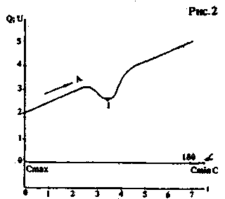
Q - quality factor in arb. units
U - high-frequency voltage in arb. units
a is the angle of rotation of the condenser rotor C, deg.
C is the capacitance of the capacitor.
t is the time of rotation of the capacitor rotor, arb. units
v.1 - moment of resonance.
RA. Resistor R5 sets the required sensitivity of the device. With the help of the R4VD4 chain, an additional positive bias is applied to the source VT2. With resistor R3, the arrow of the device is set to any place on the scale that is most convenient for observing the moment-resonance.
| MHz range |
0,12-0,5 |
0,495-2,0 |
1,95-8,1 |
8,0-30 |
| WITH* |
pf |
1000 |
1000 |
1000 |
| L |
μg |
5300 |
309 |
20 |
Working with the device is very simple. The investigated oscillatory circuit is connected with the GIR circuit. The tuning knob quickly moves the capacitor from the maximum capacitance position to the other extreme position. If there was no LED flash, there is no resonance in this subrange.
If a flash of the LED was observed, setting the tuning knob approximately to the position at which there was resonance, set the maximum sensitivity of the measuring device with resistor R5, set the arrow to the middle of the scale with resistor R3 and, slowly turning the GIR tuning knob, determine the moment of resonance in the traditional way. For a more accurate determination of the moment of resonance, a "stretching" tuning capacitor with an air dielectric C5 with a capacity of 2 ... 15 pF is used, the handle of which is displayed on the front panel of the GIR. The value of the resonance frequency is read on the scale of the frequency meter.
The values of L, C* are given in the table. Radio amateurs themselves can calculate the values of L, C * and winding data L based on the selected cutoff frequencies of the subbands, the available variable capacitor and frames for the inductors. The method for calculating L, C* has been repeatedly cited in the technical literature, for example [4,5].
When repeating the GIR according to this scheme, it must be taken into account that a periodic disruption of oscillations (relaxation) can be observed in the low-frequency range due to the high quality factor of the circuit and the large POS. You can get rid of this either by including a 47 - 200 Ohm resistor in the tap from the coil, or by making a tap not from the middle of the coil, but closer to the "ground" end. It should also be noted that the LED will flash every time the capacitor rotor rotates rapidly in the direction of increasing capacitance, because. in this case, the RF voltage on the circuit decreases.
Literature
1. Transistor GIR // Radio. - 1971. - N 5. - S. 55.
2. Borisov V. GIR // Radio. - 1974. - N3. - S. 53.
3. Gavrikov V, Prakhin P. Amplitude-stable local oscillator // Radio. - 1984. - N 2. - S. 22.
4. Biryukov S. On the calculation of oscillatory circuits of generators // Radio. - 1992. - N11-S. 23.
5. Malinin PM Handbook of radio amateur-designer. - M.: Energy, 1978.
Author: V. Demyanov, Kremenchug; Publication: N. Bolshakov, rf.atnn.ru
 See other articles Section Measuring technology.
Read and write useful comments on this article.
<< Back
 Latest news of science and technology, new electronics:
Machine for thinning flowers in gardens
02.05.2024
In modern agriculture, technological progress is developing aimed at increasing the efficiency of plant care processes. The innovative Florix flower thinning machine was presented in Italy, designed to optimize the harvesting stage. This tool is equipped with mobile arms, allowing it to be easily adapted to the needs of the garden. The operator can adjust the speed of the thin wires by controlling them from the tractor cab using a joystick. This approach significantly increases the efficiency of the flower thinning process, providing the possibility of individual adjustment to the specific conditions of the garden, as well as the variety and type of fruit grown in it. After testing the Florix machine for two years on various types of fruit, the results were very encouraging. Farmers such as Filiberto Montanari, who has used a Florix machine for several years, have reported a significant reduction in the time and labor required to thin flowers.
... >>
Advanced Infrared Microscope
02.05.2024
Microscopes play an important role in scientific research, allowing scientists to delve into structures and processes invisible to the eye. However, various microscopy methods have their limitations, and among them was the limitation of resolution when using the infrared range. But the latest achievements of Japanese researchers from the University of Tokyo open up new prospects for studying the microworld. Scientists from the University of Tokyo have unveiled a new microscope that will revolutionize the capabilities of infrared microscopy. This advanced instrument allows you to see the internal structures of living bacteria with amazing clarity on the nanometer scale. Typically, mid-infrared microscopes are limited by low resolution, but the latest development from Japanese researchers overcomes these limitations. According to scientists, the developed microscope allows creating images with a resolution of up to 120 nanometers, which is 30 times higher than the resolution of traditional microscopes. ... >>
Air trap for insects
01.05.2024
Agriculture is one of the key sectors of the economy, and pest control is an integral part of this process. A team of scientists from the Indian Council of Agricultural Research-Central Potato Research Institute (ICAR-CPRI), Shimla, has come up with an innovative solution to this problem - a wind-powered insect air trap. This device addresses the shortcomings of traditional pest control methods by providing real-time insect population data. The trap is powered entirely by wind energy, making it an environmentally friendly solution that requires no power. Its unique design allows monitoring of both harmful and beneficial insects, providing a complete overview of the population in any agricultural area. “By assessing target pests at the right time, we can take necessary measures to control both pests and diseases,” says Kapil ... >>
| Random news from the Archive Samsung ePoP Memory
06.02.2015
Samsung Electronics has started mass production of the industry's first ePoP (package-on-package) memory, a single memory package that includes 3GB LPDDR3 DRAM memory, a 32GB eMMC board, and a controller. Designed for premium smartphones, the slim ePoP memory module integrates all major memory components into a single package that can be placed on top of a mobile processor without taking up extra space.
Overall, the new ePoP memory module is an optimal "single-packet" memory solution to meet the market's needs for high speed, high power efficiency and compactness, Samsung said. The 3GB LPDDR3 DRAM mobile memory inside the ePoP package provides 1866MB/s I/O data transfer rate and supports 64-bit I/O bandwidth.
In terms of design, ePoP memory saves a significant amount of space inside, allowing smartphone manufacturers to use the freed space for other components, such as batteries.
"Due to its thinness and special heat-resistant characteristics, Samsung's ePoP smartphone memory occupies only 225 square millimeters (15x15 mm), which is the same size as a mobile application processor," the company said.
The traditional PoP memory module (also 15mm x 15mm), which includes the mobile CPU and DRAM, as well as a separate eMMC package (11,5mm x 13mm), covers 374,5 square millimeters. Replacing this component with a Samsung ePoP module reduces the total footprint of this equipment by approximately 40%."
The single package design also does not exceed the upper limit of 1,4 mm for the semiconductor package height.
Original equipment manufacturers can use Samsung's ePoP memory in various mobile devices. The company already offers a similar one-pack solution for portable devices, the so-called "portable memory". At the same time, the new configuration designed for phones can be easily modified and used not only in premium smartphones, but also in other complex mobile devices, such as premium tablets, in cooperation with international mobile device companies, emphasized in Samsung.
|
Other interesting news:
▪ The more dust, the warmer
▪ Revealed the secret of flickering lightning
▪ Energy Efficient GPS Processor for Wearable Electronics from Broadcom
▪ South Korea launches 5G network
▪ Fast blood test
News feed of science and technology, new electronics
 Interesting materials of the Free Technical Library:
▪ website section LEDs. Article selection
▪ article At the very blue sea. Popular expression
▪ article Where and when were beer boilers converted into armored vehicles? Detailed answer
▪ article Logistics Economist. Job description
▪ article Thunderstorm, static and antenna. Encyclopedia of radio electronics and electrical engineering
▪ article Protection device for a three-phase electric motor from open-phase mode in case of an open circuit of the power fuse. Encyclopedia of radio electronics and electrical engineering
Leave your comment on this article:
 All languages of this page
Home page | Library | Articles | Website map | Site Reviews

www.diagram.com.ua
2000-2024


 Arabic
 Bengali
 Chinese
 English
 French
 German
 Hebrew
 Hindi
Hindi Italian
 Japanese
 Korean
 Malay
Malay Polish
 Portuguese
 Spanish
 Turkish
 Ukrainian
 Vietnamese