|
|


 Arabic
 Bengali
 Chinese
 English
 French
 German
 Hebrew
 Hindi
Hindi Italian
 Japanese
 Korean
 Malay
Malay Polish
 Portuguese
 Spanish
 Turkish
 Ukrainian
 Vietnamese
|
ENCYCLOPEDIA OF RADIO ELECTRONICS AND ELECTRICAL ENGINEERING
The choice of wiring, methods of laying wires and cables. Electrical parts. Encyclopedia of radio electronics and electrical engineering
Encyclopedia of radio electronics and electrical engineering / Electric installation work Wires, cables and cords are the main element of any electrical wiring, to which all kinds of additions rely: various electrical components or electrical installation devices. These include switches and switches, electrical connectors (sockets and plugs) and clamps, lamp and starter sockets, various types of fuses. By way of installation Switches classified into switches for open and hidden installation. In addition, there is a division of switches into single-key, double and triple (Fig. 7).
Switches for open installation are mounted, as a rule, when laying open electrical wiring; they are attached to wooden sockets with a thickness of about 10 mm using screws. For the installation of flush-mounted switches, an additional part is a steel or plastic box: first, a box is built into the wall, to which the switch itself is attached with spacers and screws. Single-key switches are designed to close one circuit (for example, to turn on / off one lamp). Paired ones are most often used for five-arm lamps, when one key turns on two light bulbs, the other - three, and both - all five (Fig. 8).
Paired switches are also convenient for separate bathrooms, as well as if there are two consumers of electric current in the kitchen or the same bathroom: a lighting device (ceiling lamp) and an exhaust ventilation system installed in a window or ventilation window. The purpose of the built-in switches is to close and open three electrical circuits (they are very convenient in small apartments when lighting the kitchen, bathroom and toilet rooms). On the basis of the design features of the mechanism, the switches can be keyboard, toggle, rotary, push-button and cord. At present, for domestic needs, switches are produced mainly of a keyboard type, but the presence of push-button or rotary switches in the apartment is not excluded. Portable lighting fixtures (such as floor lamps) often use pull cord switches. But even switches of the same type can differ significantly in their kinematic schemes (Fig. 9).
The schemes of operation of the presented switches are quite simple. In a rocking mechanism with a compression spring (Fig. 9, a), when the key (1) is pressed, the ball (3), compressing the spring (2), passes through the swing axis of the rocker arm (4), and under the action of the spring slides along the arm of the rocker, throwing it to the opposite position, thereby breaking or connecting the circuit. In a rocking mechanism with a tension spring (Fig. 9, b) frame (2), which fixed on the switch key and pressed against the base (5) by a spring (4), can swing around the axis and come into contact with the plate (1) or open this contact. The spring, by means of a bracket (3), when the frame passes through the vertical plane, throws the frame to the "on" position or back, depending on the pressure on the upper or lower part of the key. Switches of this design are placed in a flat case with one, two or three large keys in one block. They can be used for both hidden and open wiring. Their contact is made of cermet with the addition of silver, which ensures reliable operation of the switch. Rated current - up to 4 A. The cam switch with a flat spring (Fig. 9, c) is very simple. Like the toggle switch (Fig. 10), it is often used in household appliances.
The highest rated current of ordinary household switches is 6 A; if the contacts of the switch are made of cermet, then 10 A. The cause of the most likely troubles that can occur in switches is the voltaic arc that occurs at the moment of breaking the contacts or vibration of the contact plate after the contact hits the contact. This leads to riveting of the contacts, abrasion and melting of the switch parts. When choosing a new circuit breaker, it is more expedient to prefer a design that provides a quick separation of the contacts to a distance that does not support the burning of a voltaic arc, since with a slow separation of the contacts, the voltaic arc lasts a considerable time and causes the greatest wear on the circuit breaker. Sometimes a household appliance, such as a table lamp, starts flashing, and the switch makes a characteristic crackle that is easy to hear. This is a clear indication of a switch failure that needs to be urgently repaired or replaced. The crackling comes from the constant sparking between the contacts due to their unreliable fit to each other in the on state. Such a malfunction may occur due to insufficient force of the toggle spring, oxidation or contamination of the contacts. It should be noted that the cam mechanisms in switches are more often subject to such trouble, since they do not provide a quick break in the circuit, as well as a stable and sufficient force for contact. It is better to change such switches in advance for keyboards with a rocker mechanism with an extension spring, without waiting for them to fail. Most electrical appliances are connected to the network using plug connections: sockets and plugs. One of the parts of such connections, namely the socket is an integral part of the wiring. The designs of sockets are not as diverse as the designs of switches, and yet sockets are distinguished: for open and hidden installation; two- and three-pin; for connecting plugs with round and flat pins; for connecting one and two plugs (Fig. 11).
Sockets for open and hidden installation are attached to the walls in the same way as switches of the same types. The most reliable of them are sockets with a clamping spring (Fig. 12).
To increase safety (especially if the sockets are located low enough from the floor, and there are small children in the house), the sockets are equipped with a swivel washer or a moving damper; these devices securely cover socket openings when the outlet is not in use. The rated current for sockets in a 220 V network is 10 A; for a network with a voltage of 380 V - 25 A. Early in the morning, late in the evening or at night, that is, at night, it can be difficult to find a switch or outlet. For the convenience of consumers, many manufacturers of electrical components produce sockets and switches with a neon light bulb built into their housing. But if ordinary electrical installation parts are installed in an apartment (house), then it is easy to equip them with a neon light bulb on your own. All that is needed for this is to solder pieces of insulated wire to the terminals of the light bulb and connect them in series with quenching resistance (1-5 MΩ) to the terminals of the switch or socket (Fig. 13).
When an electrical appliance (lamp or other current receiver) is turned on, the circuit that includes the neon light is open and the light is off; but as soon as the lamp is turned off or the plug is removed from the socket, the circuit closes and the light starts to glow. In order for the luminous light bulb to be visible, it is necessary to drill a hole with a diameter of 5-6 mm in the non-translucent cover of the switch housing and paste a piece of plexiglass with a semicircular head into it, press the neon bulb canister to the plexiglass from the inside of the switch housing. If the housing is made of transparent material, it is enough to place the light bulb under the cover or in any other place inside the switch housing. To minimize the amount of wire bending when installing flush-wiring sockets and switches, they are designed to allow wires to be connected to them after the switch or socket has been secured to the socket on the wall panel. If the wiring is open, switches and sockets should be installed on wooden sockets, to which they are attached with two screws. Hand stains constantly appear on the wallpaper near the switch. This can be easily avoided if a thin (1-1,5 mm) Plexiglas plate with a hole for the switch mechanism is laid between the switch cover and the wallpaper. The size of the plate is approximately 130 x 180 mm. The next piece of wiring is cartridge, which is necessary to connect lighting lamps to the network. Since there are two types of lighting lamps - incandescent and fluorescent, there are also two types of lampholders for them. For incandescent lamps, threaded cartridges are used, which differ in size: lamps with a power of up to 60 W can be connected to an E14 (small base) and E27 (medium base) cartridge; lamps up to 200 W - to the E27 cartridge; lamps with power from 300 to 1500 W - to the E40 cartridge (large base). If it is written on the lamp base: 14 mm, then only an E14 type cartridge should be used for it, if it is 27 mm, then an E27 type cartridge will do. The constructive solution of the cartridges is not the same: there are hanging cartridges with a nipple, with an eye for hanging, a wall cartridge with an inclined flange, etc. The scheme for mounting the cartridge in the wiring is shown in fig. 14.
For each of these series of lamps, a temperature is defined that is considered elevated: for E14 it is more than 110 ° C, for E27 - more than 140 ° C. Cases of cartridges for work in such conditions are made of ceramics or heat-resistant plastic. Such modes of operation occur when using lamps with upper power values inside small closed shades. Whatever the case of the threaded cartridge - porcelain or plastic, but contacts and contact clamps are mounted only on porcelain inserts. This is due to the fact that during the glow of the bulb, the socket-lamp connection can heat up to very high temperatures (up to 200 ° C). For fluorescent lamps, cartridges can be rack-mount, round or cap. They are usually made of plastic, since the glow of a fluorescent lamp does not lead to a significant increase in the temperature of the joints. Perhaps the only reason for damage to the cartridges is poor contact of the wire clamps or poor contact of the lamp with a contact petal damaged by a spark that often occurs in a contact connection. The cartridges are disassembled on the spot before they are removed. It is necessary to disconnect the wires, loosen the locking screw inside the housing (in the bottom thread) or unscrew the lock nut from the threaded tube. After that, you can remove the cartridge from the lamp tube. Branching boxes are installed in the places of branches and branchings of the electrical wiring (Fig. 15), and in the places where the wires are connected in separate sections of the hidden wiring, junction boxes are installed. Boxes can be metal or plastic. The difference between junction boxes and junction boxes lies in the different number of holes on the side walls: junction boxes have three or four holes, junction boxes have two (in principle, junction boxes can be installed as junction boxes). A lid is included with the boxes.
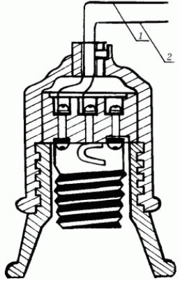
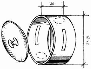
Circuit breakers - a mandatory part of any electrical wiring. They are electrical circuit protection devices. There are two main types of fuses - automatic and with fuses (Fig. 16).
Recently, it is circuit breakers that have become widespread, they are much easier to operate: when the protective device is triggered, it is enough to press the button on the switch head (of course, after turning off all electrical appliances or those that caused the circuit breaker to trip), and wiring will return to working condition. Fuses with fusible inserts - yesterday's electrical engineering; however, if the house is old, then the electricity meters in it are probably equipped with fuses with fuses. They consist of a porcelain cork, inside of which there is a wire rated for a current of 6 or 10 A; if the current in the circuit reaches the limit value, the wire melts and the circuit is de-energized. The inconvenience of such fuses is that they are essentially disposable, since after operation the fuse must be replaced. Fuses with fusible links are more advanced. They are a hollow ceramic case with a thread on the base, in the hole of which a replaceable tubular insert with a soldered thin, easily burnt wire is placed; when such a fuse blows, only this insert must be replaced, and not the entire fuse. It should be remembered that it is strictly forbidden to repair failed fuses. If they burn out, in no case should you wind the wire around the cork, as a strong current can pass through it, which can cause a fire. By the way, according to statistics, a third of fires in Russia occur precisely because of the use of such bugs in fuses. It is always necessary to have spare plugs for 6 or 10 A. It is forbidden to repair and adjust protection devices of all types on your own. They are sealed at the factory. When a fusible link burns out, it can only be replaced with a factory-made one. In addition to fuses, electrical wiring can be additionally equipped with residual current device (RCD). The structure and principle of operation of the RCD are simple (Fig. 17).
The device is connected in series with a differential current transformer, a threshold element on a sensitive magnetoelectric relay and an actuator - a high-current contact group on a spring wire. During normal operation of electrical wiring and electrical appliances connected to the network, the operating current, flowing in the forward and reverse conductors of the primary winding of a differential transformer, induces oppositely directed but equal magnetic fluxes (F1 and F2) in its magnetic circuit, which compensate each other; therefore, in the secondary winding of the transformer, the current is 0 and the threshold element does not work. In the event of a short circuit (or current leakage to the ground, or when a person touches a bare wire and other current-carrying parts of wiring or devices), the balance of magnetic fluxes is disturbed, current appears in the secondary winding of the transformer and the magnetoelectric relay of the threshold element instantly reacts by acting on the actuator, which , acting on the principle of a release, de-energizes the protected circuit. It may seem that RCDs actually duplicate fuses with fuses or circuit breakers, because they perform the same function of protecting electrical wiring in the event of a short circuit or network overload. But this is not entirely true: the advantage of RCDs over conventional fuses is that, in addition to protecting electrical wiring from possible fire and failure of electrical appliances, it also protects a person, minimizing the risk of electric shock. If it is decided to include a residual current device in the electrical wiring circuit of your home, then you should remember that there are two types of such devices: electronic - dependent on the supply voltage and electromechanical - independent of the supply voltage. The disadvantage of electronic RCDs is that their performance depends on the presence of current in the circuit. But, unfortunately, very often in electrical networks there is a break in the neutral wire, the circuit breaks, but the voltage in the network remains; a person, assuming a de-energized electrical wiring, touches current-carrying parts, which leads to electric shock. Electromechanical RCDs are devoid of this drawback and operate regardless of the presence or fluctuation of voltage in the network. Therefore, it is advisable to use electronic RCDs only as an additional safety net for other protective devices in the most dangerous areas of electrical wiring, for example, in especially wet rooms. It remains only to add that the installation and repair of RCDs can only be trusted by qualified specialists who are licensed to perform electrical work - they will help with the choice of device. So that there is no doubt about the quality of the device, you need to focus on the following information: - among domestic RCDs that meet the requirements of the State Standard and Glavgosenergonadzor and have proven themselves in practice, two devices can be distinguished - ASTRO * RCD manufactured by Technopark-Center OJSC (electromechanical) and RCD-2000 manufactured by OAO Research Institute "Proektelectromontazh" (electronic); - among imported RCDs, NFI 5 SZ 3227 (from the "Siemens" concern) have proven themselves well in the Russian market; DX / D40 (from the French company "Legrand"); F 360, F 370, DS 640/DS 650 (from ABB). The last (in the list, but not least) element of the electrical wiring is electrical energy meter: single-phase - for metering electricity for domestic needs and three-phase, if, for example, a home workshop is equipped with machines with electric motors. Author: Korshevr N.G.
A New Way to Control and Manipulate Optical Signals
05.05.2024 Primium Seneca keyboard
05.05.2024 The world's tallest astronomical observatory opened
04.05.2024
▪ Space satellite will help in the fight against drought ▪ Self-learning brain for smartphones and tablets
▪ section of the site Tips for radio amateurs. Selection of articles ▪ article Two minutes of hate. Popular expression ▪ article Stalnik prickly. Legends, cultivation, methods of application ▪ article Masses of pitch. Simple recipes and tips ▪ article T-bridge in the bass amplifier. Encyclopedia of radio electronics and electrical engineering
Home page | Library | Articles | Website map | Site Reviews
www.diagram.com.ua |


 Leave your comment on this article: