|
|
ENCYCLOPEDIA OF RADIO ELECTRONICS AND ELECTRICAL ENGINEERING Once again about UW3DI. Encyclopedia of radio electronics and electrical engineering
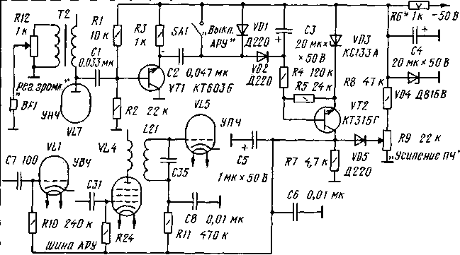
Encyclopedia of radio electronics and electrical engineering / Civil radio communications For decades, "old men" - transceivers of the UW3DI design have served us faithfully, remaining for many the only opportunity to spend time on the air with enthusiasm. Over the past years, there have been many publications in various literature on the refinement and improvement of these transceivers. With a focus on a beginner radio amateur and based on my own experience, I propose some changes in the design and scheme of the original author's publication of the UW3DI-1 transceiver (see "Radio", 1970, No. 5, 6). Automatic gain control The introduction of the AGC system will significantly improve the operation of the transceiver. The AGC scheme of the UW3DI-II transceiver was taken as a basis (with some additions, see Fig. 1). In this and subsequent figures, the positional designations of elements without ratings correspond to the positional designations of the circuit in the author's publication with a slight modification - L7 is replaced by VL7, RZ - by short circuit, etc. VL6) - on 9K4P. It should be noted that before installing the 6K13P lamp into the transceiver, it is necessary to swap the conductors connected to the legs 6 and 1 of the lamp socket. The pinouts of the lamps 5K6P and 4Zh6 P are the same. The low-frequency signal from the VL7 ULF lamp through the emitter follower on the transistor VT1 is fed to the AGC detector (diodes VD1 and VD2). Capacitor C3 determines the AGC delay time, Zener diode VD3 determines the AGC threshold. Resistor R9 carry out manual gain control. At the loudest signals, the voltage on the AGC bus reaches -10V. The AGC unit is assembled on a printed circuit board made of foil fiberglass. It is installed in the basement of the chassis. UHF input loop It is possible to improve the selectivity of the receiving path by installing a high-quality narrow-band circuit at the UHF input (Fig. 2). Coil L1 is made on a ferrite magnetic circuit with holes (the so-called transfluxor), which is used, for example, in television indoor antennas. It contains 50 turns of PEV-2 wire 0,23 mm. The tap for the 80 m range is made from the 25th turn, for the 40 m range - from the 10th turn (counting from the end of the coil connected to the common wire). The antenna communication coil is one turn of the same wire.
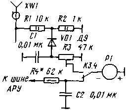
Coil L2 is made on a frame with a diameter of 15 mm and has 20 turns of silver-plated wire with a diameter of 0,7 mm. Winding step - 1 mm. The taps are made from the 1st and 12th turns, counting from the end of the coil connected to the common wire. S-meter and exit indicator This refinement (Fig. 3) allows using the transceiver's measuring device as an S-meter when receiving and an output indicator when transmitting. To switch the measuring device, a free group of short circuit relay contacts is used.
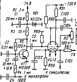
The milliammeter is replaced by a microammeter with a total deflection current of 50-100 μA. When receiving, the device is calibrated according to the generally accepted method by selecting resistor R4, and when transmitting, by trimming resistor R3 (at the maximum signal at the transceiver output). When initially setting up the P-circuit (by selecting capacitors C53 - C55), a 150-200 mA milliammeter should be connected to the anode circuit of the output stage lamp. In the future, the setting of the output circuit is controlled by the output indicator. microphone amplifier To work with low-impedance microphones, you need to add a cascade on the transistor VT1 (Fig. 4). VOX, AntiVOX systems and VL14 lamp are excluded. The output of the capacitor C 105, which is freed at the same time, is connected to a common wire, as shown in Fig. four.
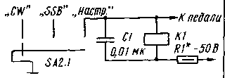
The right terminal of the R87 resistor is connected to the bus, which combines the cathodes of the lamps used only in the transmission mode. Variable resistor R5 adjust the output level of the microphone amplifier. Mode switching The transceiver has three modes: CW, SSB and tuning. When setting up, the transceiver is switched on for transmission with the SA2 switch (Fig. 5).
When working CW and SSB, a pedal is used for this. Resistor R1 is selected depending on the type of relay used. Author: Vladimir Zhitkov, Ust-Donetsk, Rostov region; Publication: N. Bolshakov, rf.atnn.ru
Machine for thinning flowers in gardens
02.05.2024 Advanced Infrared Microscope
02.05.2024 Air trap for insects
01.05.2024
▪ Current behaves like a liquid ▪ Recycling old plastic into soap ▪ Passenger aircraft without windows
▪ section of the website Audiotechnics. Article selection ▪ article Reassessment of values. Popular expression ▪ article Does the weather affect health? Detailed answer ▪ article Chief Power Engineer. Job description ▪ article Electric fence scheme. Encyclopedia of radio electronics and electrical engineering
Home page | Library | Articles | Website map | Site Reviews www.diagram.com.ua |


 Arabic
 Bengali
 Chinese
 English
 French
 German
 Hebrew
 Hindi
Hindi Italian
 Japanese
 Korean
 Malay
Malay Polish
 Portuguese
 Spanish
 Turkish
 Ukrainian
 Vietnamese


 Leave your comment on this article: