|
|


 Arabic
 Bengali
 Chinese
 English
 French
 German
 Hebrew
 Hindi
Hindi Italian
 Japanese
 Korean
 Malay
Malay Polish
 Portuguese
 Spanish
 Turkish
 Ukrainian
 Vietnamese
|
ENCYCLOPEDIA OF RADIO ELECTRONICS AND ELECTRICAL ENGINEERING Light installations. Encyclopedia of radio electronics and electrical engineering
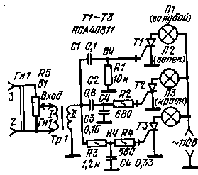
Encyclopedia of radio electronics and electrical engineering / Color and music settings In our country and abroad, various light-acoustic devices are widely used, which create lighting effects in time with the melody of the music program being played. Abroad, such devices are called "Color Organs", "Dance Lights", "Rhythmicons", etc. Most of the devices are made in the form of attachments to receivers, electric and tape recorders. As you know, the work of light and acoustic installations is based on changing the color and brightness of the glow of lighting devices placed behind a special transparent screen, in time with the change in tone and volume of the sound system. The control voltage for the light-acoustic set-top box is removed from the voice coil of the loudspeaker head or from the ULF linear output, which is part of the electro-acoustic installation. It is generally accepted that the sound signals of the bass group (lower frequencies), occupying the frequency band up to 150-.200 Hz, should correspond to red; medium frequencies (200-1000 Hz) - yellow or green; higher frequencies (more than 1 kHz) - blue or cyan. These color effects are created by light sources whose glass bulbs are coated with a clear lacquer of the appropriate color. The brightness of the channel light sources is regulated by transistor or thyristor controllers. The number of such rulers should be equal to the number of channels, usually three. Often on the pages of foreign publications one can find descriptions of four-, five- and more-channel light-acoustic installations. In these cases, either the so-called background channels of violet or pale yellow color are introduced, which work constantly or at the moments when all other channels are turned off, or they are allocated to a separate channel, controlled by frequencies above 4-XNUMX kHz. In accordance with the above principles of construction, light-acoustic installations must contain multi-channel filters that divide the input signal spectrum into several frequency bands (3, 4 or 5), channel controllers that work in conjunction with channel light sources of a certain color, and a power source. Since light-acoustic effects are most noticeable when the electric power of channel light sources is at least 50-60 W, it is advisable to power such installations only from the mains. Transistor prefixes that create light-acoustic effects are low-power, often fail, require painstaking adjustment, although they allow you to get a smooth reproduction of tonality and intensity transitions. The most common thyristor prefixes. A simple light-acoustic prefix on thyristors Figure 1 shows a schematic diagram of a simple thyristor light-acoustic attachment containing three. color channels and powered by AC mains 1'27 V. To increase the input control voltage taken from the voice coil of the speaker head, as well as to isolate the input circuit and the AC mains at the input of the set-top box, a step-up transformer Tr1 is included, which is recommended to use output transformer from a tube network receiver of class II or IV, including its secondary winding to the input, and the primary winding to the filter.
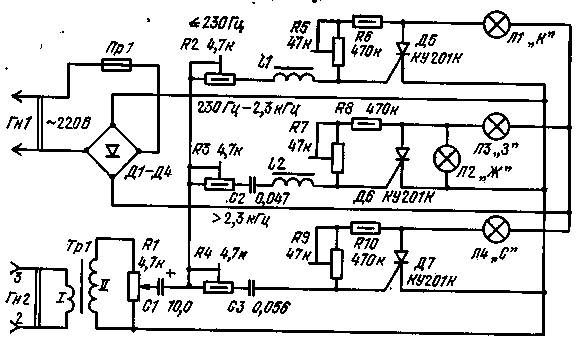
The prefix according to the scheme of Fig. 1 is capable of ensuring the simultaneous operation of all three channels when using one 100 W lamp in each of them. Such high voltages and powers require additional precautions when setting up and working with the attachment. All capacitors must be rated for an operating voltage of at least 200V. Thyristors used as controlled switches must withstand reverse blocking voltages at least 1,5-2 times greater than the supply voltage. The allowable average current of the thyristors must be at least the maximum current consumed by the cascade lamp. In this case, at least 1 A. In view of the foregoing, when repeating the prefix, thyristors of the KU202I or KU202L type can be used. In the presence of high-voltage thyristors of the KU202N type, it is possible to increase the supply voltage to 220 V AC. In this case, the power of the lamps in each channel can be increased to 200 watts. If the radio amateur only has low-voltage thyristors, for example, of the KU202B, KU202V or KU202G type, which allow reverse voltages up to 25, 50 and 100 V, respectively, the set-top box should be powered through an adjustable autotransformer. Of course, incandescent lamps must be rated for a lower voltage. And, as practice shows, even with such a complication of the set-top box circuit, its glow is much more noticeable than that of transistor set-top boxes. However, such attachments have a number of disadvantages. We present the main ones. 1. In some cases, especially when working at high volume, all channel lamps turn on and off at the same time, in time with the change in volume. At the same time, changing the tone of the sound does not affect the operation of the lamps of various channels. Typically, this is due to very high input levels and imperfect crossovers, which have an out-of-band slope of only 6 dB/oct. You can eliminate this drawback by including an additional resistor R5 at the input of the set-top box. With the help of a variable resistor, it is possible to adjust the signal level at the input of crossover filters in such a way that, with the set ULF output power, the channels are clearly turned on and off. The signal voltage at the input of the primary winding of the transformer should be equal to 0,2-0,5 V. If the signal voltage is higher, the normal operation of the set-top box is disrupted. The additional variable resistor should be a 51-100 ohm wire-wound resistor. For the convenience of summing up the signal, it is recommended to use the SG-3 type connector as an input jack. In all cases, reliable isolation of the circuit board with thyristors and separation filter parts from the input socket and variable resistor must be ensured. 2. There is a large uneven glow of the lamps. They either burn with full heat, or do not glow at all. Sometimes the screen goes completely blank, most often this happens when the sound volume drops a lot. This disadvantage is a direct consequence of the simplicity of this design. It can be partly eliminated by introducing a fourth, background channel, which remains on while the other three are turned off completely. The design of such an improved version of the console is given below. 3. Incandescent lamps do not give a bright glow, flashing is noticeable. This disadvantage is explained by the use of thyristors with an asymmetric output characteristic. This means that such thyristors behave like controlled half-wave rectifiers, while for the normal glow of standard incandescent lamps it is necessary to use both half-cycles - positive and negative. This shortcoming can be eliminated in two ways. Firstly, by supplying the anode circuits of the thyristors from the network through a full-wave rectifier in a bridge circuit. If for this purpose a rectifier with four diodes of the D226 type is used, then the total current consumed from the network should not exceed 0,6 A, which corresponds to the use of lamps with a power of not more than 50 W in each channel. As practice shows, in most cases this is enough. Secondly, thyristors with a symmetrical output characteristic can be used. In this case, an additional rectifier in the power circuit is not required. Light-acoustic prefix with a background channel This set-top box was developed by a Bulgarian radio amateur. It eliminates many of the shortcomings of a simple prefix, which was discussed above. The prefix has three main frequency channels with frequency bands from the lowest to 230 Hz (red lamps); 230 Hz to 2,3 kHz (green lamps); above 2,3 kHz (blue lamps). The schematic diagram is shown in Fig.2. It can be seen from the figure that the thyristor anodes are powered from a 220 V AC network through a full-wave rectifier based on four diodes of the D246 type, rated for a current of up to 5 A. The input control signal is fed to the Gn2 socket, then through the step-up transformer Tr1 to the inputs of isolation filters. To correct the signal level at the inputs of crossover filters, a variable resistor R1 is used. In this case, it may be non-wire.
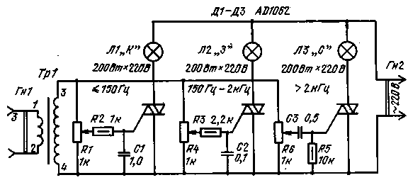
Crossover filters are made using inductors. To equalize the sensitivity of the thyristors of different channels, additional resistors are used, connected between the anodes and the control electrodes of the thyristors. One of the resistors is a trimmer. A feature of the circuit is the presence of a background channel on the L2 lamp, the bulb of which is colored yellow. This lamp is connected in parallel to the anode and cathode of the D6 thyristor. It glows only when the D6 thyristor is closed and all the voltage from the rectifier output is divided approximately equally between the lamps of the mid-frequency (green) and background (yellow) channels. In addition, each crossover filter has trimming resistors R2-R4. With their help, the transmission coefficients of each filter are corrected to achieve the correct operation of the thyristors in accordance with the spectral composition of the control signal. Coils LI and L2 are wound on frames, into which are then inserted cores ШЗХ'6 from output transformers for a pocket receiver. The coils are wound with PEL-1 0,1 wire and contain 750 and 500 turns, respectively. Light-acoustic prefix on symmetrical thyristor Figure 3 shows a schematic diagram of a simple light-acoustic set-top box with three channels, each of which includes a 200 W lamp. The prefix was described on the pages of a Romanian youth magazine. Channel separation frequencies are 150, 800 Hz and 2 kHz. The design has much in common with the attachment in Fig. 1: the simplest crossover filters, a step-up transformer at the input of the crossover filters, lamps and thyristors with a symmetrical output characteristic. Symmetrical thyristors D1-DZ are controlled in the same way as thyristors with an asymmetric characteristic, but they do so during both half-cycles of the AC mains voltage.
As can be seen from Fig. 3, the prefix contains corrective variable resistors at the input of each crossover filter, which allows you to adjust the operation of the prefix depending on the musical content of the program being listened to and watched. When repeating the design, you can use high-voltage symmetrical thyristors of the KU208G type, which allow reverse voltage at the anode up to 400 V. Information about other details of the attachment can be gleaned from the descriptions of the two previous attachments. Light-acoustic installations are still relatively rare devices for the listener and viewer, so they usually attract the attention of many. Decorative screens of light and acoustic installations can be installed in a residential area or in a club. Of particular interest is the use of two light-acoustic installations, working in conjunction with a stereo system. On the setup screens, the unbalance of the amplifier channels is clearly distinguished, the features of the channels when playing sounds from moving instruments. And, finally, all the attachments described are essentially the simplest electrical signal spectrum analyzers that can be used without acoustic installations. For example, if you connect the output of a pulse generator to the input of the set-top box, then the number and brightness of the channels will depend on the duration of the pulses and their repetition rate. Literature:
Publication: N. Bolshakov, rf.atnn.ru
Machine for thinning flowers in gardens
02.05.2024 Advanced Infrared Microscope
02.05.2024 Air trap for insects
01.05.2024
▪ Electrical stimulation of the brain helps to cope with a stroke ▪ Chronic lack of sleep can damage memory
▪ section of the site History of technology, technology, objects around us. Article selection ▪ article Seize the moment! Popular expression ▪ article Why can't I create a folder called con in Windows? Detailed answer ▪ article Auto mechanic. Standard instruction on labor protection
Home page | Library | Articles | Website map | Site Reviews
www.diagram.com.ua |

 Leave your comment on this article: