|
|


 Arabic
 Bengali
 Chinese
 English
 French
 German
 Hebrew
 Hindi
Hindi Italian
 Japanese
 Korean
 Malay
Malay Polish
 Portuguese
 Spanish
 Turkish
 Ukrainian
 Vietnamese
|
ENCYCLOPEDIA OF RADIO ELECTRONICS AND ELECTRICAL ENGINEERING Design of electronic control gear for fluorescent lamps. Encyclopedia of radio electronics and electrical engineering
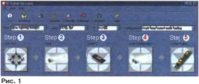
Encyclopedia of radio electronics and electrical engineering / Radio amateur designer The development of high-frequency electronic ballasts (electronic ballasts) for fluorescent lamps is a complex engineering task with many unknowns, requiring solid knowledge and considerable time. To simplify its solution, International Rectifier has placed on its website the Ballast Designer program - a computer-aided design of electronic ballasts on specialized microcircuits of its own design, which makes the competent design of these devices accessible even to a beginner radio amateur. The Ballast Designer program frees the developer of electronic ballasts (often referred to as "electronic ballasts") for lighting fluorescent lamps from the routine work of selecting elements, long and laborious calculation of the values of circuit components and winding products, making it possible to compensate for the lack of experience in the process, which is especially valuable for amateur developments. A set of documents received in just a few minutes is sufficient for the manufacture of the calculated product. The program is available free of charge at (8,3 MB). The bda.zip archive must be unpacked into a separate folder on the computer's hard drive, then found in it and run the Ballast Designer program or the Setup installer. In both cases, the computer will begin the installation process, after which the "Ballast Designer" shortcut will appear on the "Desktop". To launch the program of the same name in the operating mode, just click the "mouse" on the shortcut. It is necessary that in the Windows settings ("My Computer" - "Control Panel" - "Language and Standards" - "Numbers") a dot is specified as a decimal separator, and not a comma familiar to a Russian-speaking user. Otherwise, everything will end with an error message on the screen and the program will stop working. Upon successful launch, the window shown in Fig. 1.
Two design procedures are offered - standard and extended. By default, the standard one will be used, giving the user the opportunity to "dial" the appropriate option from three input node circuits, five types of controller chips and several dozen types of lamps connected to the electronic ballast according to seven different circuits. In the process of automatic design, an electronic ballast circuit will be synthesized that provides optimal values for the amplitude and frequency of the voltage applied to the lamp in the heating, ignition and combustion modes, maximum lamp life, lighting quality and device efficiency. The advanced design procedure gives the user the ability to actively influence the decisions made by the program by changing more than 20 parameters at will, including frequency, voltage and current of the lamp in various modes, and the ratings of the main components. The possibility of constructive calculation of chokes according to the specified electrical parameters is provided To perform a standard procedure, it is enough to press in turn the five on-screen buttons located under the inscriptions "Step 1" - "Step 5" ("Step G - "Step 5"), choosing one of the proposed options at each step. Step 1 - selection of the mains voltage rectifier circuit. The "Select Line Input" window opens on the screen. By moving the slider in the lower part of the window, one of the variants of the rectifier unit is selected (Fig. 2, a-c). His scheme will appear in the window, next to it - a list of several options for acceptable limits for changing the mains voltage. In the list, select the line with the most suitable option.
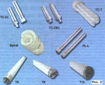
To complete the step, it remains to press the "Select" button. The selected limits will be displayed in the "Input" box above "Step 1". They can be changed at any design stage by clicking the arrow button next to the mentioned box and selecting a new option from the drop-down list. The program provides similar possibilities (drop-down lists of options in the "Lamp", "Control 1C", "Configuration" boxes) for changing the parameters set at other steps of the standard design procedure. The schemes of the bridge rectifier (Fig. 2, b) and the rectifier with voltage doubling (Fig. 2, c) are no doubt well known to readers. About the scheme in fig. 2, and with an active power factor corrector (Eng. Power Factor Corrector, PFC) it is necessary to tell in more detail. The pulsed power supplies that have become widespread today, which include electronic ballasts, are not a very successful load for the power grid. The fact is that they consume not a sinusoidal, but a pulsed current with a peak value many times greater than the effective one. The high-frequency components of the spectrum of current pulses create powerful interference with radio and television reception and can even lead to failures of computers connected to the same network. The recently adopted recommendations of the International Electrotechnical Committee IEC 1000-3-2 establish very low harmonic limits (up to the 39th) in the spectrum of current consumed from the network at a power factor close to 1. The requirements of the standards in force in the CIS countries in this respect while much softer, but their tightening can be expected in the near future. An active power factor corrector solves the problem by making the drawn current close to a sinusoidal shape. The corrector is a pulse boost converter-voltage stabilizer. Thanks to its work, a powerful pulse of the charging current of the capacitor C1 (Fig. 2, a) is split into many short pulses distributed over the period in such a way that their average value changes almost according to a sinusoidal law. The resulting high-frequency components of the current are smoothed out by a filter not shown in the simplified diagram. When powered from a 220 V mains, the normal output voltage of the corrector is 400 V. It is stabilized, so the brightness of the lamp glow is practically independent of mains voltage changes over a wide range. The Ballast Designer program usually builds a corrector control unit based on the L6561 chip, a specialized PFC controller. The IR2166, IR2167 electronic ballast controllers are equipped with built-in corrector control units, which, according to the company, are superior in parameters to specialized microcircuits. Step 2 - select the type and power of the lamp. The "Select Lamp" window opens on the screen. In it, by moving the slider, one of the lamps shown in Fig. 3 groups.
Each of them has lamps of different power. The names of the groups adopted in the program are conditional. The correspondence between them and the letter indices in the designations of the most common lamps of some manufacturers can be determined from the table (the lamps of the Spiral group are not produced by the companies listed in it)
Groups T5, T8, T12 include conventional linear fluorescent lamps (fluorescent lamps) with a bulb diameter of 16, 26 and 38 mm, respectively, including those with increased efficiency and improved spectral composition of light. It is possible to expand the list of lamps by the user. To do this, just select the "User Lamp" group in the "Select Lamp" window and click the "Edit List" button. A window for editing the list of lamps and their parameters will open. Step 3 - selection of the electronic ballast controller chip. The "Select Target 1C" window opens on the screen. By moving the slider, one of the proposed microcircuits is selected. If Adobe Acrobat Reader is installed on the computer, by clicking on the "Datasheet" button in the upper part of the main window (see Fig. 1), you can view the description and reference data of the selected microcircuit in English. In the version of the program that was in force at the time of preparation of the article, the following microcircuits were offered: IR21571 - for the simplest electronic ballasts, relatively easy to adapt to various types of fluorescent lamps. Russian translation of datasheet-a for this chip. IR2157 - provides optimal modes for starting cathode preheating, ignition and lamp operation, and automatic mode change. It is equipped with units for monitoring the status and protection of lamp filaments, protection against low supply voltage, against failure when changing a lamp, against thermal overload, against electrostatic discharges and some other means that ensure reliable operation of electronic ballasts and its automatic restart after exiting an emergency. IP2156 - "younger sister" IP2157, differs from it in the absence of some protective functions. IR2159 - the same functionality as IR2157, additionally allowing you to adjust the brightness of the lamp by changing from 0,5 to 5 V of the control voltage supplied to a special input. The limits of brightness change (in the range of 1 ... 100%) are set by resistors connected to the outputs of the microcircuit. A method for controlling the power supplied to the lamp has been implemented, which does not require an isolation transformer. Russian translation of datasheet-a on a chip. IR2166, IR2167 - are equipped, as already noted, with built-in power factor corrector controllers with dynamic adaptation to the electronic ballast operating mode. Provides a total harmonic coefficient of less than 10% and a power factor of more than 0,99 when powered from a network with a nominal voltage of 120 and 220 V, which exceeds the requirements of the standards of most European countries and exceeds the performance of many specialized corrector control microcircuits. Step 4 - selection of the number of lamps and the scheme of their connection to the electronic ballast. The "Select Lamp Configuration" window appears on the screen, in which it is necessary, by moving the slider, to select the appropriate scheme with one or two lamps. All possible options are shown in Fig. 4, a-zh.
Step 5 - automatic design of electronic ballasts. After pressing the "Design Ballast" button, a window with the International Rectifier logo appears on the screen, which shows the progress of the design process, which takes only a few seconds. Upon completion, windows open, one of which contains a schematic diagram of the designed device. An example of the synthesized circuit is shown in fig. 5. It differs from the original only in the use of conventional symbols for elements familiar to readers of the magazine. Circuits highlighted in color should be made with as short and thick wires as possible. The types and denominations of the elements on the original diagram are absent, instead, their list is given in a separate window (eng. Bill of Materials, BOM).
Another one or several (according to the number of elements) windows contain data on the inductive elements available in the designed electronic ballast. An example of such a window is shown in Fig. 6. In addition to the nominal inductance, maximum current and temperature, all the data necessary for the manufacture of a choke or transformer are indicated here: recommended standard size (core size) and brand of magnetic circuit material (core material), non-magnetic gap length (gap length), number of turns (turns) and the wire diameter of the winding. Even a sketch of the design and layout of the conclusions is given.
To switch to the advanced design procedure in the main program window (see Fig. 1), click the "Advanced" button. As a result, the main window will be transformed into the one shown in Fig. 7.
It provides access to the values of various parameters that can be changed during the design process. The position of the operating point of the lamp (in voltage-frequency coordinates) in various modes and the trajectory of its movement when they change can be obtained graphically (Fig. 8). It is possible to open windows for designing inductive elements ("Inductor" button) or selecting element ratings that set the operating mode of the electronic ballast controller ("Program 1C" button).
In preparing the article, information found on the Internet at the following addresses was used: , , , , , . Author: Yu.Davidenko, Lugansk, Ukraine
A New Way to Control and Manipulate Optical Signals
05.05.2024 Primium Seneca keyboard
05.05.2024 The world's tallest astronomical observatory opened
04.05.2024
▪ E-paper with optimal color reproduction ▪ HP Omen Mindframe Headset with Cooling Ears ▪ Lifetime charging for Tesla electric vehicles
▪ section of the site For a beginner radio amateur. Article selection ▪ article Money for a barrel. Popular expression ▪ Physalis article. Legends, cultivation, methods of application
Home page | Library | Articles | Website map | Site Reviews
www.diagram.com.ua |


 Leave your comment on this article: