|
|


 Arabic
 Bengali
 Chinese
 English
 French
 German
 Hebrew
 Hindi
Hindi Italian
 Japanese
 Korean
 Malay
Malay Polish
 Portuguese
 Spanish
 Turkish
 Ukrainian
 Vietnamese
|
ENCYCLOPEDIA OF RADIO ELECTRONICS AND ELECTRICAL ENGINEERING About the correction of the S-meter in the CB radio station. Encyclopedia of radio electronics and electrical engineering
Encyclopedia of radio electronics and electrical engineering / Civil radio communications The S-meter built into the radio station allows you to fulfill the usual request from the side of the correspondent: evaluate his signal in S-scale points. The corresponding levels of high-frequency voltage at the 50-ohm antenna input of the receiving radio station are shown in Table 3. Unfortunately, in the communication equipment that comes to us from abroad, S-meters, as a rule, remain "raw", not exposed. Although it is not difficult to bring the S-meter readings to normal * (the stations have a special adjusting resistor for this), this can only be done if there is a high-frequency generator with a good attenuator. As a rule, a radio amateur does not have such equipment. On fig. 25 shows a schematic diagram of the generator, using which you can check, and if necessary, correct the S-meter readings of your radio station at home. The oscillator frequency (VT1, etc.) is set by the ZQ1 quartz resonator. It must, of course, be within the operating frequency range of the station. Better - in its middle. The high-frequency voltage at the emitter of the transistor VT1 depends on the generator supply voltage, which can be changed with a trimming resistor R3. Resistors R4 ... R12 are an attenuator - a normalized high-frequency signal attenuator that reduces Uin \u0,85d 25 V the signal level at its input - to Uout \u50d XNUMX μV - the output signal level (with a XNUMX-ohm load connected to it - input resistance radio stations). Table 3
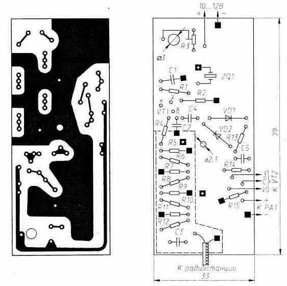
Thus, by connecting such a generator to the antenna input of the station, we will give it an 8-point signal and we will only have to set these 8 points on the scale of its S-meter. In the Yosan 2204 radio, for example, this is done by adjusting the VR602 trimmer. If the radio amateur does not have a high-frequency voltmeter that allows you to set the desired voltage at the input of the attenuator, then such a voltmeter is easy to make. Its schematic diagram is shown in the same fig. 25 (elements C2, VD1, VD2, C5, R13, VT2, R14, R15 and PV1). PV1 is a conventional digital or pointer voltmeter with an input resistance of at least 100 kOhm. On its "=U" scale, adjust R3 and set the desired 0,85 V. On fig. 26 shows the printed circuit board of the generator with an RF voltmeter, made of double-sided foil fiberglass with a thickness of 1,5 mm. The foil on the side of the parts is used only as a screen and a neutral wire (a "-" power source is connected to it). To skip the conclusions of parts in it, ring-shaped samples are made by etching or countersinking. Connections to the null foil of "grounded" leads are shown as black squares. All resistors in the calibrator are MLT 0,125 or similar to the same power (S2-23, OMLT, etc.). Wire resistors (generally, resistors with a conductive layer in the form of a spiral) cannot be used in the attenuator R4 ... R12: their inductance will introduce an uncontrolled component into the divider. The required resistance for the attenuator is selected using a digital ohmmeter.
The installation of random resistors that only nominally have the required resistance can lead to the fact that the attenuator attenuation will differ from the calculated one by 30 ... 40% or more. The attenuator is separated from other elements of the generator by a screen with a tin shield or a box 7 ... 8 mm high, soldered to the null foil. On fig. 26 its position on the board is shown by a dashed line. Capacitors C3 and C4 here are of the type KD, C1, C2 and C5 - KM-6. The ZQ1 quartz resonator must operate at the fundamental frequency (in such resonators, the frequency is indicated in kHz, and not in MHz, as in those excited on the fundamental harmonic). In order to avoid possible disruption of oscillations, it is better not to connect the resonator case to anything. The assembled board must be placed in a metal box of suitable dimensions; suitable, for example, a tin box from under the bouillon cubes.
The generator is connected to the antenna input of the radio station with a short coaxial cable with an appropriate connector at the end. Of course, the signal level at the output of the calibrator may be different. But for this, changes will need to be made to its attenuator. Table 4
Let's present the same attenuator in a different form (Fig. 27, a). It has four T-sections that are easily visible. The first, unbalanced, is made up of resistors R4, R5 and R6. Having a 50-ohm load at the output (input resistance of the next section), it will lower Uin = 0,85 V - the signal level at its input - up to 25 mV at this load. The next three sections are symmetrical and identical: each of them has Rin = Rout = 50 Ohm and with a 50-ohm load at the output contributes its own 20 dB to the total attenuation (see Fig. 27, b and table 4). Any of these three sections can be tuned to some other attenuation. It will only be required in accordance with table 4 to replace Ra and Rb in it. Since the input-output resistance of the section remains unchanged (these are the same 50 Ohms), the appearance of new Ra and Rb will obviously not affect the attenuation introduced by other sections of the attenuator. That is, having somehow changed the attenuation in the section, we will change the attenuation of the entire attenuator in the same way, by the same amount. So, having halved the attenuation of only the last section of the attenuator (from 20 to 14 dB), setting it in accordance with Table 4: R10= R12=33,3 ohm and R11=20,8 ohm up to 50 points. After making certain changes in the sections, you can return to the previous attenuator structure. It is only necessary to sum up the values of the series-connected resistors, replacing them with one. So the calibrator shown in Fig. 25 will become 9-point if you change the values of three resistors in it, setting R10 \u74,3d 41 Ohms (33,3 + 11), R20,8 \u12d 33,3 Ohms and RXNUMX \uXNUMXd XNUMX Ohms. Without the topological transformation made above, all this would have to be taken on faith. The rather high voltage at the output of the calibrator - 25 or 50 µV - is chosen here because as it decreases, in an attempt, for example, to check the S-meter readings in the middle of the S-scale or even at its beginning, shielding becomes more and more important. all elements of the calibrator, even individual sections of its attenuator. External pickups to the station may also have an effect here (the self-shielding of many of them is far from ideal); in any case, these pickups should be 2...3 points weaker than the signal coming from the calibrator. In conclusion, we note that although the described calibrator is intended for correcting the readings of an S-meter already available in the radio station, it can also be useful in calibrating self-made S-meters. It is only necessary to supplement it with an attenuator with variable signal attenuation (see Radio, No. 11, 1997, p. 80), taking, of course, measures to thoroughly shield this entire path. *) If the scale of the S-meter is only offset. But there are S-meters, the readings of which can be combined with Table 3 only in certain positions. This is a design defect. In modern radio stations, it is usually unremovable. Publication: cxem.net
A New Way to Control and Manipulate Optical Signals
05.05.2024 Primium Seneca keyboard
05.05.2024 The world's tallest astronomical observatory opened
04.05.2024
▪ Perhaps there are planets inhabited by intelligent dinosaurs ▪ The driver is hindered not by a mobile phone in his hands, but by talking on it
▪ section of the site Encyclopedia of radio electronics and electrical engineering. Article selection ▪ article Assistant florist. Drawing, description ▪ article Does gravity act on the moon? Detailed answer ▪ article Stonecrop rock. Legends, cultivation, methods of application
Home page | Library | Articles | Website map | Site Reviews
www.diagram.com.ua | |||||||||||||||||||||||||||||||||||||||||||||||||||||||||||||||||||||||||||||||||||||||||||||||||||||||||||||||||||||||


 Leave your comment on this article: