|
|
ENCYCLOPEDIA OF RADIO ELECTRONICS AND ELECTRICAL ENGINEERING Simple vibrator HF antennas and the possibility of their modernization. Encyclopedia of radio electronics and electrical engineering
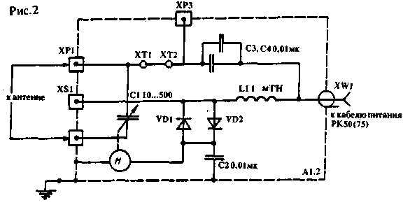
Encyclopedia of radio electronics and electrical engineering / HF antennas Most designs of such antennas are described in the literature [1, 2], and it is precisely because of their simplicity that they are used by many shortwave radios. Their main disadvantages are also well known, to which, first of all, a very limited bandwidth should be attributed. The consequence of this is a significant influence of atmospheric conditions on the resonant frequency and, consequently, on other parameters of the antenna. Shortened vibrators with inductive or capacitive loads are most susceptible to such influence, which often makes them unsuitable for operation in areas with sudden weather changes. In the case of using broadband antennas with absorbing resistances, part of the transmitter power is dissipated by the resistance. It is quite possible to increase the efficiency of even an existing design with a slight complication of the antenna matching system with the feeder. 1. Remote control of the resonant frequency and the matching system of the KB antenna. As part of various designs of amateur short-wave antenna-feeder devices and their matching systems, it is widely used. use capacitors of variable capacity with an air dielectric (KPI). Most often they are used to adjust the effective length of the vibrator and adjust various matching devices. At the same time, the KPI itself often has to be installed directly next to the vibrator itself, i.e. It turns out to be remote from the operator. This situation creates difficulties, especially when using one antenna on several bands. Remote control of such a KPI allows you to equalize the efficiency of the antenna at different points in the range, and in some cases, rebuild it to work on a different range. Operational adjustment of the resonant frequency of the vibrator or its matching system allows you to get the best results on the low-frequency HF bands of 160 and 80 m, where conventional non-adjustable antennas experience significant power losses when operating at the edges of the range. On fig. 1 and 2 shows a diagram of a simple device that allows remote adjustment of the capacitance of KPI C1, which is part of the antenna-matching device. The scheme of the device SA2550 of the company "HEATHKIT" [XNUMX] was adopted as a basis. The device consists of two blocks. Antenna unit A1 is installed directly next to the vibrator itself. It is he who is the most important part of the whole device. The main element here is the KPI C1 with an air dielectric, controlled by a reversible DC motor with a low number of revolutions. The whole device is enclosed in a metal case, which must be sealed. The variant of this block A1.1, shown in the figure, fully corresponds to SA2550, in which the KPI C1 rotor must rotate around without restrictions and be well isolated from the axis of the motor or gearbox. The initial capacitance C1 is 10 ... 15pF, the maximum is from 500 pF at 28 MHz to 1700 pF at 1,9 MHz. The gap between the KPE plates, as well as the parameters of other parts of both blocks, are selected depending on the maximum power of the transmitting device and the available engine. It should only be noted that all chokes installed in the device must be made with a wire of the appropriate diameter (depending on the current consumed engine) and not have side resonances on amateur bands. This can be achieved by winding them in sections and progressively. The case of the A1 unit must be grounded and measures must be taken to prevent moisture from entering it, especially if it is installed in an open area. It is best to close it with another case made of dielectric material. The A2 control unit is installed indoors near the radio station itself. It serves as a power supply and control unit for the reversible motor in the A1 unit. The electrical connection between the blocks is carried out by means of a coaxial cable of the required length and wave impedance. This cable carries both the high-frequency voltage from the TX to the antenna or from it to the RX, as well as the DC control voltage. Three-position switch B1 controls the operation of the engine, i.e. supply of a constant voltage of different polarity, which determines the direction of rotation of the motor. To isolate the DC source and the motor from the high-frequency voltage, LC filters and blocking capacitors are used in the blocks, and to prevent the control voltage from entering the output stage of the PX transmitter and the antenna, capacitors C6, C7, C8 are used, the dielectric strength of which is also selected taking into account the maximum transmitter power. To increase the reactive power of capacitors, you can use their series connection if a capacitor with the required power and voltage is not available.
Figure 2 shows the second version of the diagram of block A1.2. It differs from the previous one in a few big ways. The choice of the required version of the A1 block depends on the type of antenna used and its matching system. Figures 3 - 8 show various schemes for connecting KPE C1 to different types of asymmetric vibrators.
Figure 3 shows how, by making an asymmetric vibrator 5 - 15% longer than a conventional quarter-wave vibrator and using this device, you can get the ability to tune the antenna to resonance at any point in the operating range. In addition, the longer vertical vibrator is better matched to the coaxial cable.
Figure 4 shows an application of the device with a quarter-wave vertical vibrator fed by a gamma matching device. In this case, C1 acts as a trimmer capacitor in the matching device and also makes it possible to improve the matching of the vibrator with the power cable at various points in the range. Figure 5 shows the connection diagram of the A1.2 block for operation with an L-shaped vibrator, designed for one of the ranges (160 or 80m). On these ranges, with a short length of the vertical part, the L-shaped vibrator has a low input resistance, and to match it, it is necessary to use an additional inductor or step-down transformer. They are connected to the terminals ХР2, ХРЗ and the block body, and the jumpers ХТ1, ХТ2 are removed.
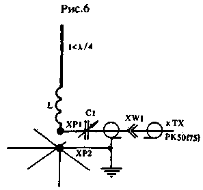
Figure 6 shows the connection of C1 to a vibrator with a length of less than a quarter of a wavelength, which has an extension coil installed in the working part of the vibrator. The inductance of this coil is chosen in such a way that the resonant frequency of the vibrator with a shorted KPE C1 is somewhat lower than necessary.
The same applies to the antenna shown in Fig. 7 and described in [3]. Due to the significant shortening, such antennas have a very narrow bandwidth, and this device will allow you to effectively use it at any point in the range.
Figure 8 shows the connection diagram of the A1.2 block to an inclined vibrator made from a piece of ribbon cable. The electrical length of the vibrator is selected depending on the cable used and is close to a quarter wavelength. On a range of 160 m, it is permissible to use a ribbon wire for electrical and radio wiring with two cores with a diameter of at least 0,5 mm, located at a distance of several millimeters and having good quality insulation. The shortening factor must be taken into account.
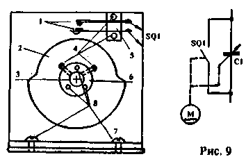
As already noted, the requirements for the maximum capacitance of KPI C1 depend on the bands on which the antenna is used. Since it is rather difficult to select KPIs with a small initial and maximum capacitance of 1000 pF or more necessary for low-frequency ranges, additional switching contacts can be used. They can also be useful if it is necessary to disable KPI C1. This version of the refinement of block A1.2 is shown in Fig. 9, where the numbers indicate: 1 - group of switch contacts; 2 - disk made of insulating material; 3-axis KPE C1; 4 - 8 - mounting bolts MZ, M4; 5 - insulating plate for fastening contacts; 6 - metal sleeve for fastening the disk to the KPE axis; 7 - metal wall or body of KPE C1.
The device can be used in conjunction with the antenna described in "RL" N12/92, p.38. OK3TDC [5] pointed out the possibility of using an 80m antenna for operation on the 40m and 20m bands by connecting capacitors of a certain capacitance in parallel to the supply line. The use of block A1.2 allows you to do this without a mechanical switch. Another possible variant of the scheme for including KPI C1 of block A1.2 in a full-sized or shortened frame is shown in "RL" N6 / 92, p.45, fig.2. In this case, it is included in the box break. Literature
Author: V.Efremov; Publication: cxem.net
Machine for thinning flowers in gardens
02.05.2024 Advanced Infrared Microscope
02.05.2024 Air trap for insects
01.05.2024
▪ Cloud connected microcontroller ▪ Satellite chip for mobile phones ▪ The stadium generates electricity ▪ Digital TV Tuner for Xbox One
▪ section of the website Experiments in Physics. Selection of articles ▪ article by Alain (Emile-Auguste Chartier). Famous aphorisms ▪ article Which of the buildings of antiquity is the most famous? Detailed answer ▪ article Flat-leaved vanilla. Legends, cultivation, methods of application
Home page | Library | Articles | Website map | Site Reviews www.diagram.com.ua |


 Arabic
 Bengali
 Chinese
 English
 French
 German
 Hebrew
 Hindi
Hindi Italian
 Japanese
 Korean
 Malay
Malay Polish
 Portuguese
 Spanish
 Turkish
 Ukrainian
 Vietnamese


 Leave your comment on this article: