|
|


 Arabic
 Bengali
 Chinese
 English
 French
 German
 Hebrew
 Hindi
Hindi Italian
 Japanese
 Korean
 Malay
Malay Polish
 Portuguese
 Spanish
 Turkish
 Ukrainian
 Vietnamese
|
ENCYCLOPEDIA OF RADIO ELECTRONICS AND ELECTRICAL ENGINEERING An economical receiver for a CB radio station. Encyclopedia of radio electronics and electrical engineering
Encyclopedia of radio electronics and electrical engineering / Civil radio communications The ability of a portable radio to be ready to receive a correspondent's call at any time depends on its power consumption in standby mode. Usually it is only 10...30 hours of work. The next step is to replace the power supply. Such "autonomy" extremely limits the scope of this technique. On fig. 7 shows a schematic diagram of an economical receiver for a single-channel CBC radio station. Transistors VT1 and VT2 are included in the radio frequency amplifier (URCH), its circuits L2C3 and L3C4 are tuned to fk - the frequency of one of the communication channels allowed in this range (today there are about 160 of them). The balanced mixer and the local oscillator are made on the DA1 chip. The local oscillator frequency is set by the ZQ1 quartz resonator, it must be lower or higher than the radio channel frequency by 465 kHz. The frequency response of the IF path is formed by the L5C9 circuit and the ZQ2 piezo filter. The DA2 chip performs the functions of an intermediate frequency amplifier (IFA), a frequency detector (L6C12 is its reference circuit) and an audio frequency preamplifier (UCH). The main UZCH is made on an operational amplifier DA3 with a symmetrical emitter follower (transistors VT3, VT4) at the output. Turning on/off UZCH depends on Iupr - current in the resistor R20: UZCH is off if lupr=0. On the operational amplifier DA4, operating in the mode of a high-frequency audio filter (HFC filter), and the transistor VT5 (electronic key), a noise suppressor is made, which turns on the ultrasonic frequency only when a correspondent appears in the channel, suppressing the high-frequency noise of the free channel with its carrier. The receiver is mounted on a printed circuit board 55x88 mm (Fig. 8), made of double-sided foil fiberglass 1,5 mm thick. The foil on the side of the parts is used only as a neutral wire and a screen: in the places where the conductors pass, circles with a diameter of 1,5 ... resistors, etc. are shown as black squares. Coils L2 and L3 - 18 turns of wire PEV-2 0,33 each - are wound in a row on frames with a diameter of 5 mm, having holes with an MZ thread for a carbonyl core. Communication coils L1 and L4, 3 turns of wire PEVSHO 0,27 each - are wound over the loop coils at their "cold" (high voltage) ends. These coils are mounted on the board as shown in Fig. 9.
Coils L5 and L6 are wound in cups from the Selga radio. They contain 135 turns of wire PEVSHO 0,1 (outlet in L5 - from 45 turns, counting from above). The cups are glued with BF-2 glue, and then glued to the printed circuit board as shown in Fig. 10.
The L5C9 and L6C12 circuits of the IF path are tuned with M3x12 carbonyl cores, for which there are holes with the corresponding thread in the printed circuit board. All fixed resistors of the receiver are of the MLT-0,125 type, trimmer R24 - SPZ-38a. Capacitors: C14 - K50-30; C21, C27 - K50-35; C16 - K53-18V; C3, C4, C6-C8, C11, C13, C3O - KD-1; C9, C12 - KM, K10-176 (M750 groups). Switch "reception-transmission" SA1 - type PKn61. Radio receiver controls: R14 - volume, R27 - squelch threshold, SA1 - local-far reception, SA2 - squelch switch. Adjustments: R24 - amplification (quality factor) of the VZCh filter, R18 - amplification of the UHF (Ku \u18d R17 / R4), RXNUMX - amplification of the URF in local reception mode. There are no special features in the receiver settings. First, tune its IF circuits according to the generator set to a frequency of 465 kHz (weakly connecting it with the L5C9 circuit; control by signal at pin 13 of the DA2 microcircuit); then - the circuits L2C3 and L3C4 according to the generator set to fk - the frequency of the radio channel. The setting of the L6C12 frequency detector circuit is corrected on the air, listening with the SHP turned off (SA2 is closed) the FM stations operating in this channel.
Turning on the SHP, set the gain of the VHF filter according to the noise of the free channel, for which the slider of the resistor R27 is placed approximately in the middle position and, by moving the slider of the resistor R24, they find its position in which the UHF is switched. This completes the squelch setup. It remains only to make sure that the on/off of the UZCH can be controlled using the resistor R27, and turning off the UZCH with it (without a large margin), and that when a correspondent appears in the channel, the UZCH will turn on on its own. The sensitivity of the receiver is not worse than 2 μV. It retains its performance when the supply voltage drops to 4V.
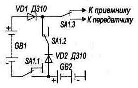
On fig. 11 shows a possible switching of the supply battery, which makes it possible to use a transmitter designed for* power supply from a 10 ... 12-volt source in tandem with such a receiver. Note that in this case the station will operate in standby mode for 400...700 hours. And when using batteries with a capacity of 1,2 Ah - and even more so. Radio stations of this kind have their own scope. This is a connection in long-distance hikes, in professional and amateur expeditions, in the protection of remote farmlands, in hunting, etc. In a word, where a portable radio station from a city toy that only supplements an apartment telephone (it is in the city that its many channels, high selectivity, dynamic range are needed and no significant autonomy is needed), becomes the only means of communication that allows a group of people to maintain between a contact, as quickly as possible to provide assistance to those in need. It is also not indifferent, of course, that the cost of such a station will be much lower than the price of the most mediocre foreign "multi-channel". In any case, for a radio amateur designer. Publication: cxem.net
A New Way to Control and Manipulate Optical Signals
05.05.2024 Primium Seneca keyboard
05.05.2024 The world's tallest astronomical observatory opened
04.05.2024
▪ Apple is the most valuable company in history
▪ site section Indicators, sensors, detectors. Article selection ▪ article Leibniz Gottfried. Biography of a scientist ▪ article Where and when was the first international film festival held? Detailed answer ▪ article Working with a circular saw. Standard instruction on labor protection ▪ article Resistors. Color marking. Encyclopedia of radio electronics and electrical engineering
Home page | Library | Articles | Website map | Site Reviews
www.diagram.com.ua |


 Leave your comment on this article: