|
|


 Arabic
 Bengali
 Chinese
 English
 French
 German
 Hebrew
 Hindi
Hindi Italian
 Japanese
 Korean
 Malay
Malay Polish
 Portuguese
 Spanish
 Turkish
 Ukrainian
 Vietnamese
|
ENCYCLOPEDIA OF RADIO ELECTRONICS AND ELECTRICAL ENGINEERING Radio forget-me-not. Security system. Encyclopedia of radio electronics and electrical engineering
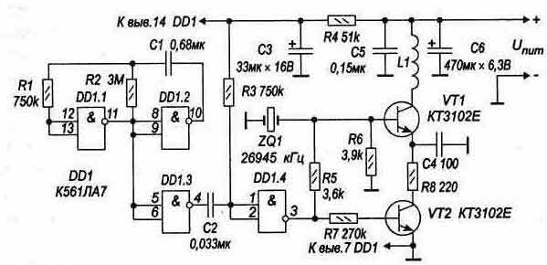
Encyclopedia of radio electronics and electrical engineering / Security devices and object signaling A micropower radio transmitter, located in a briefcase, backpack, etc., and a special radio receiver from the owner, which reacts to the disappearance of contact with "radio" things due to their loss or, possibly, theft, can constitute a security system capable of detecting the loss at its earliest stages. Micro power transmitter Schematic diagram of the "forget-me-not" radio transmitter is shown in fig. 1. The mode of operation of its high-frequency part (VT1, ZQ1, R5, R6, R8, C4, L1) sets a device that includes a multivibrator (DD1.1, DD1.2, R1, R2, C1), excited at a frequency f = l / 2 * R2 * Cl \u0,25d 0,3 ... 1.3 Hz, and the shaper (DD1.4, DD3, R2, C3), transforming one of the fronts of the multivibrator meander into a pulse with a duration timp \u2d R20 * CXNUMX \uXNUMXd XNUMX ms.
Table 1
The transmitter operates in pulsed mode. Only when a voltage equal to Upit appears at the output of DD1.4 will the conditions for its excitation be created: the electronic key (transistor VT2) in the power circuit will open, and the necessary initial current will appear in the base of the transistor VT1. The time for the transmitter to enter the operating mode and, accordingly, the front of the radio pulse emitted by it is ~ 4 ms*. In the pause between pulses, the power consumption of the high-frequency part of the transmitter is reduced to almost zero. To reduce the power consumption of the controls, a resistor R1 is introduced into the power supply circuit of the DD4 microcircuit, which reduces the voltage across it to the value Upit, at which the through currents of the CMOS structures that make it up become quite small. As a transistor VT1, any silicon n-p-n-transistor with a cutoff frequency of at least 200 MHz can be taken. The main requirement for the transistor VT2: saturation voltage Uke us Ј 0,2 V. If this transistor has a lower current gain compared to the KT3102E, then to put it into saturation mode, it will be necessary to reduce the resistance of the resistor R7 accordingly. Capacitor capacitance C3 \u5d (10 ... 5) timp / R3 (C5 - in μF, timp - in ms, RXNUMX - in kOhm). Coil L1 - the "magnetic" antenna of the transmitter - is wound coil to coil on a glass-textolite plate 20x8 and 1,5 mm thick. It has 30 ... 35 turns, wire - PEVSHO 0,25 ... 0,3. The ZQ1 quartz resonator must have a frequency approved by Gossvyaznadzor for security systems: 26945 or 26960 kHz**. It is important that this be its main resonance (in a resonator whose operating frequency is the harmonic of the main resonance, it will be indicated differently: 26,945 or 26,960 MHz). When using a harmonic resonator, the choke-antenna L1 will need to be replaced with a full-fledged oscillatory circuit, switched on so that its resistance, given to the collector of the transistor VT1, does not exceed 1 ... 1,5 kOhm (shunting the circuit with a resistor is possible).
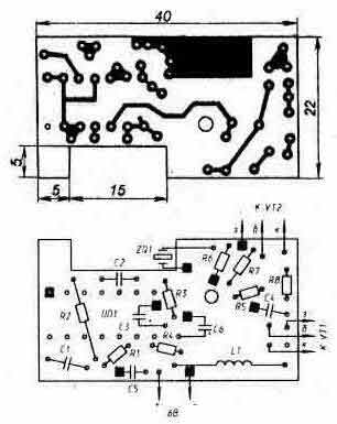
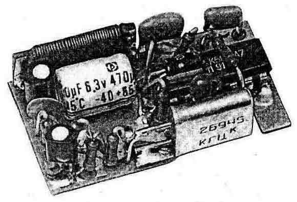
The transmitter works without any external antenna: at "forget-me-not" distances, it is simply not necessary. Any 6-volt battery can serve as a power source. The dependence of the current consumed by the transmitter Icon on the voltage of the power supply Upit is shown in Table 1. All elements of the microtransmitter are placed on a printed circuit board made of double-sided foil fiberglass 1 mm thick (Fig. 2). The foil on the side of the parts (not shown in the figure) serves only as a common wire-screen (the "-" GB1 is connected to it), in the places where the conductors pass, it has selections of circles with a diameter of 1,5 ... 2 mm. Connections to it with the conclusions of resistors, capacitors, etc. are shown in black squares. The ZQ1 quartz resonator is installed in the cutout of the printed circuit board and fixed by soldering to the zero-foil of the "grounded" output. Oxide capacitors C3 (dimensions 04x8 mm) and C6 (08x12 mm) are mounted in the "lying" position: C3 - above the microcircuit, C6 - on the board (Fig. 3). All resistors - MLT-0,125. Capacitors: C1 - K10-176, C2 and C6 - KM-6, C4 - KD.
A miniature 6-volt battery of the E11A type (010,3x16 mm) with an electric capacity of 33 mAh is used as a power source for the microtransmitter. There is no need for a power switch - just insert the battery into a special socket with spring-loaded contacts. The general view of the transmitter is shown in the photo (Fig. 3). Forget-me-not radio receiver made as a superheterodyne with a single frequency conversion, its circuit diagram is shown in fig. 4. The DA1 chip is a converter, the input circuit L1C1C2 of which is tuned to the frequency of the security alarm radio channel fk - 26945 or 26960 kHz, and the local oscillator frequency fg, shifted relative to fk by 465 kHz, is set and stabilized by the ZQ1 quartz resonator. The difference (intermediate) frequency signal fg=465 kHz, selected by the ZQ2 piezo filter, is fed to the input of the DA2 microcircuit, which includes an intermediate frequency amplifier, an amplitude detector and a low frequency amplifier. The operational amplifier DA3 with a transistor VT1 at the output is an energy-saving comparator that converts a low-level pulse signal into a pulse with an amplitude close to Upit. The direct and inverse inputs of DA3 receive the signal through frequency RC filters: R8*C14=300 ms, which monitors the supply voltage, and R10*C15=1ms, which significantly reduces the receiver's sensitivity to impulse noise. In the comparator, resistor R9 is especially important: the voltage drop across it is DUr9- sets the comparator threshold. So, if R9=30 kOhm, then in accordance with the distribution of the supply voltage in the divider, composed of resistors R7, R9 and R11, DUr9=30 mV and the comparator will only respond to input signals whose amplitude exceeds this value. The device that generates an alarm signal when the microtransmitter signal disappears contains a master oscillator (DD1.1, DD1.2, R16, R17, C16), which forms a meander (period tzg = 2R17 * C16), and a sound generator (DD1.3, DD1.4. 18, R19, R18, C 2), excited at the frequency fsv=l/19R18*C2. Chip DD10 - counter. A pulse of "single" amplitude at the R-input sets it to the zero state. A blocking has been introduced into the counter: when a high-level voltage appears at the CN input, it stops responding to signals coming to the CP input. In this state of the counter, the conditions for the periodic excitation of the sound generator are created: it is excited only when a high-level voltage appears at the output 1.1 DD16. If tg is set (by selecting C17 or R9) so that the pulse repetition period of the microtransmitter is less than 2tg, then the counter DD9, periodically returned to zero by the signals of the microtransmitter, will not be able to go to position "9" and the excitation of the sound generator will not take place. When the signals of the microtransmitter disappear, the alarm signaling will obviously turn on no later than after XNUMXtzg, and when they resume, it will immediately stop. About some design features of the radio receiver. Inductance L1 is a magnetic antenna. It is wound on a M30VN ferrite rod with a diameter of 8 and a length of 40 mm ***. The winding is carried out with the MGShV-0,15 wire and has 5 turns laid in a row. The resonant capacitance of the Slice circuit and its quality factor Q little depend on the placement of the winding: Slice = 32 pF and Q = 260 if it is located in the middle part of the core; Cutoff = 34 pF and Q = 280 if the winding is 5...6 millimeters from its edge. The frequency of the quartz resonator ZQ1 is recommended to be chosen below fk. In this case, the "mirror" reception channel (fзп-=fк -2fпч ) turns out to be in a lightly loaded grid B of the civil communication range. Resistor R6, on which the sensitivity of the receiver depends (it grows with the movement of the slider R6 down - see Fig. 4), can be made trimmer - under the slot, or adjusting - with a convenient handle. The screen shown in fig. 4 by a dashed line, is intended not so much to protect the radio from external pickups (its sensitivity is relatively low), but from internal ones: the signals circulating in DD1 and DD2 have high-frequency components, which, if installed unsuccessfully, can "enter" the receiving path, turn out to be commensurate with working IF and RF signals. All fixed resistors in the radio receiver are of the MLT-0,125 type; capacitor C1 - KT4-23, C12, C17 - K50-35 or K50-40, C14 - K53-30, the rest - type KD, KM-6, K10-176, etc. The receiver is mounted on a printed circuit board 87x41 mm, made of double-sided foil fiberglass 1,5 mm thick (Fig. 5). It has three cutouts: to accommodate the supply battery, the quartz resonator and the winding of the magnetic antenna.
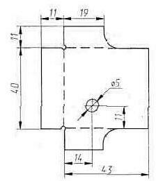
One side of the printed circuit board is used only as a common wire and screen, just as it is done in the "forget-me-not" transmitter. The screen is made of thin brass or tin, its cutting is shown in fig. 6. Three of its sides are bent along dashed lines, and the fourth - by a smooth bend on a blank with a diameter of 10 ... 11 mm.
The screen is soldered in the corners, the bottom is leveled and fixed on the printed circuit board by soldering at three or four points. When installing the screen on a board with a different configuration of conductors, it is necessary to ensure that it cannot form a short-circuited loop on the magnetic antenna: this would make the radio completely inoperable. In an unmistakably assembled radio receiver, it remains only to adjust the input circuit L1C1C2 to fk - the frequency of the selected radio channel. This can be done using a standard signal generator, one way or another connecting its output to the input of the receiver, and a voltmeter (preferably digital) with a scale of 1 ... 2 V connected to output 9 of the DA2 chip. Capacitor C1 is left in the position that will correspond to the maximum in the voltmeter readings. The standard signal generator can be replaced by a CB radio station if it has channel 39 in the B grid of the European frequency scale (this channel corresponds to a frequency of 26945 kHz), or channel 1 of the C grid of the Russian scale (26960 kHz). Tuning the input circuit of the radio receiver can also be carried out directly using the signals of a microtransmitter located 1,5 ... 2 meters: by setting the resistor R6 to the middle position, they find the position of the capacitor C1 at which the alarm disappears. An oscilloscope can be helpful when tuning the receiver with microtransmitter signals. With its help, it is easy to trace the passage of a pulse signal along the receiving path, adjust the input circuit (according to the maximum amplitude of the pulse at output 6 of the DA3 microcircuit), control the operation of the master and sound generators, etc. Table 2
The radio receiver is powered by a 6-volt 476A galvanic battery, which has small dimensions (013x25 mm) and, accordingly, a small capacity (105 mAh). Table 2 shows the dependence of the current consumed by the receiver Icon on the voltage of the power supply Upit, which makes it possible to decide on the required capacity of the power supply under conditions, for example, of multi-day continuous monitoring. *) The relatively slow excitation of quartz self-oscillators is due to the high quality factor of quartz resonators. **) In our country, only these two frequency channels are allowed for transmitting security system signals by radio. ***) M30VN-12 core or a 40 mm section of the MZOVN-D9001 magnetic antenna (the antenna breaks easily in the right place after it is lightly cut with a diamond file). Publication: cxem.net
Artificial leather for touch emulation
15.04.2024 Petgugu Global cat litter
15.04.2024 The attractiveness of caring men
14.04.2024
▪ Intel to move to tri-gate transistors in 2010 ▪ A new way to determine distances in space ▪ Snapdragon 665, Snapdragon 730 and Snapdragon 730G mobile platforms ▪ The temperature on Mars rises during the day and at midnight
▪ section of the site Signal limiters, compressors. Article selection ▪ article Two nations. Popular expression ▪ article What characteristics of a person can elephants determine by his voice? Detailed answer ▪ article Trimarans Strizh. Personal transport ▪ article Kabardian proverbs and sayings. Large selection
Home page | Library | Articles | Website map | Site Reviews
www.diagram.com.ua |


 Leave your comment on this article: