|
|
ENCYCLOPEDIA OF RADIO ELECTRONICS AND ELECTRICAL ENGINEERING Route finder. Encyclopedia of radio electronics and electrical engineering
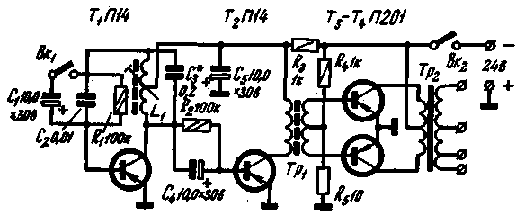
Encyclopedia of radio electronics and electrical engineering / Indicators, detectors, metal detectors Electric route finders are widely used in various sectors of the national economy. However, despite many years of improvement of these devices, even the latest developments [1, 2] have a number of significant drawbacks: One of them is poor receiver selectivity. The capacitor of the antenna circuit of the receiver does not pass signals with frequencies higher than the resonant one to the input of the amplifier. Signals of lower frequencies picked up by the antenna, including the most active pickups of industrial frequency, freely pass to the input of the amplifier and are amplified by it equally with the useful signal. For this reason, to improve the signal/noise ratio, it is necessary to significantly increase the generator power, and sometimes also introduce a pointer device into the receiver [1]. Another significant drawback of the known schemes is the bulkiness of the generator unit and especially the modulator. The described scheme of the route finder has been redesigned in order to eliminate these shortcomings. In the proposed form, the device ..allows to determine, with an accuracy of 10 cm, the axial line of telephone cables laid at a depth of up to 1 m, as well as approximately determine the depth of the cable and the location of some damage. The range of the device is 3-4 km. The device consists of two blocks - generator and receiver. The generator is powered by a 24V battery. The receiver is designed to be powered by a KBS-0,5 battery, but it can also operate from two or three FBS elements, and in extreme cases, from one FBS element. Battery capacity KBS-0,5 provides at least 100 hours of continuous operation of the receiver. scheme. Schematic diagram of the generator is shown in fig. 1. The master oscillator with a modulator is assembled on a transistor T1 (P14). With the Vk1 switch open, the transistor T1 with the L1C3 circuit in the collector circuit and the R1C2 elements in the base circuit forms one of the varieties of a three-point LC generator with an operating frequency of 1000 Hz. Partial inclusion of the circuit in the collector circuit allows you to connect significant loads directly to the collector of transistor T1 without a noticeable decrease in the quality factor of the circuit as a whole. The time constant of the base circuit is chosen close to the oscillation period. When capacitor C1 is connected using Bk1, the time constant of the base circuit increases sharply and the generator turns into a super-regenerator widely known for use in the VHF band, only in this case the modulation frequency is the required 2-3 Hz.
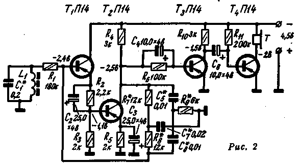
The cascade on transistor T2 (P14) is a buffer between the generator and a powerful push-pull output stage assembled on transistors T3, T4 (P201). Resistance R2 creates the necessary initial mode for the transistor T2 in terms of current; resistance R3 serves to lower the supply voltage supplied to the first two low-power transistors in order to protect against overloads according to the maximum permissible parameters (especially when working with modulation). Resistors R4, R5 create the necessary initial mode for the output stage transistors in order to maximize their use in terms of undistorted power output. The sectioned winding of the output transformer allows you to match the generator output with a load of 1-2 ohms, 50 ohms and 200 ohms. The output power of the generator is 5-8 watts. If it is necessary to increase the power of the generator, the output transistors can be replaced by P4, and between the transistor T2 and the output stage, add one stage, assembled according to the scheme with a common emitter on the transistor P201. A schematic diagram of a receiver with a magnetic antenna is shown in fig. 2.
The antenna circuit L1C1 is tuned to the frequency of the generator. The audio frequency voltage is supplied through the resistance R1 to the input of an amplifier assembled on four low-power transistors (P14 or others). The first two transistors form, together with a double T-bridge in a negative feedback circuit, a selective amplifier. At the same time, the use of bridge conductivity makes it possible to get rid of transient capacitances and obtain a temperature-stable circuit [3]. The resistance R1 is necessary to ensure normal operation of the selective amplifier with such a bridge. Two stages on transistors T3 and T4 provide the necessary gain. The initial mode of these transistors is determined by the resistances R6 and R11. Phones - high-resistance, type TON-2. Construction and details The generator is mounted on a getinax board attached at the corners to the front panel and inserted into the housing on a slide. Board dimensions 150X100 mm, thickness 2 mm. The use of a board made of insulating material allows you to place the mounting tabs in the most convenient places and thereby drastically reduce the number of connecting wires or use printed wiring. On the front panel there are Bk1I and Vk2 toggle switches, output terminals and power supply terminals. The rest of the details are fixed on the board. Powerful transistors are raised above the board with bushings and have small horseshoe-shaped aluminum heatsinks. Coil L1 contains 500+500 turns of PEL 0,1 wire and is made on the SB-3 core. The Tp1 transformer is wound on a ferrite ring with an outer diameter of 8 mm and a cross section of 2x3 mm; the primary winding contains 300 turns of PEL 0,1 wire, and the secondary winding contains 80 + 80 turns of PEL 0,15 wire. The Tp2 transformer is assembled on a core made of Sh-19 transformer steel plates, the thickness of the set is 25 mm. Its primary winding contains 130 + 130 turns of wire PEL 0,51, and the secondary - 40 + 160 + 200 turns of wire, respectively PEL 1,2, PEL 0,51, PEL 0,33. The receiver, together with the antenna circuit capacitor C1, is mounted on a getinaks board 1-2 mm thick, fixed with studs inside a vinyl plastic tube with an outer diameter of 24 mm, which simultaneously serves as a holder for the housing with a magnetic antenna. This housing can be rotated up to 120° relative to the holder and fixed in any position, which is necessary for various search modes. The antenna coil is wound on a standard F-600 ferrite rod with dimensions of 140x8 mm and contains 9 sections of 200 turns each, made with PELSHO 0,15 wire; winding type "universal". At the top of the holder there is a box for the KBS battery and telephone jacks. It is desirable to select transistors T3 and T4 with b = 40-70. Setting up the device The technique for setting up the device does not differ in principle from that described by V. Lomanovich and I. Strizhevsky [2].. It is only necessary to take into account the following. The frequency of the generator is controlled by the core of the coil L1 and the selection of capacitor C3. The resistance R2 must be selected so that when the transistor T1 is turned off, the collector current of the transistor T2 is 8-10 mA. It is desirable that the transistors T3 and T4 have the same parameters. The current consumed from the batteries depends on the load and can reach 1 A. When setting up the receiver, special attention should be paid to the careful selection of bridge elements - the gain at the "carrier" frequency depends on this. It is best to follow the methodology proposed by E. Kuflevsky [3]. The mode of the first two stages is set automatically due to DC feedback, the mode of the final stages should be selected using the resistances R6 and R11 so that the voltage on the collector of transistor T3 is about a quarter of the supply voltage, and on the collector of transistor T4 - about half of this voltage. With a supply voltage of 4,5 V, the receiver consumes a current of 4-5 mA. Literature: 1. Zotov A. A. The locator of underground gas pipelines, "Gas Industry", 1962, No. 9. Author: V.Troyanovsky; Publication: N. Bolshakov, rf.atnn.ru
Machine for thinning flowers in gardens
02.05.2024 Advanced Infrared Microscope
02.05.2024 Air trap for insects
01.05.2024
▪ By talking with adults, children develop the brain ▪ No antimicrobial additives needed
▪ site section Chargers, accumulators, batteries. Article selection ▪ article Patron. Popular expression ▪ article What feature of cats' gait allows them to be more secretive? Detailed answer ▪ article Carbon copy spring. home workshop ▪ article Card curiosities. Focus Secret
Comments on the article: Galym Well, I agree. But. I applied voltage from the magneto to the damaged cable, tuned the radio to 10 kHz, found the route and damage with the help of interference. It’s even easier to tune in to the local radio station, hang up the antenna and connect the damaged cable.
Home page | Library | Articles | Website map | Site Reviews www.diagram.com.ua |


 Arabic
 Bengali
 Chinese
 English
 French
 German
 Hebrew
 Hindi
Hindi Italian
 Japanese
 Korean
 Malay
Malay Polish
 Portuguese
 Spanish
 Turkish
 Ukrainian
 Vietnamese


 Leave your comment on this article: