|
|


 Arabic
 Bengali
 Chinese
 English
 French
 German
 Hebrew
 Hindi
Hindi Italian
 Japanese
 Korean
 Malay
Malay Polish
 Portuguese
 Spanish
 Turkish
 Ukrainian
 Vietnamese
|
ENCYCLOPEDIA OF RADIO ELECTRONICS AND ELECTRICAL ENGINEERING Calculation of AC circuits. Encyclopedia of radio electronics and electrical engineering
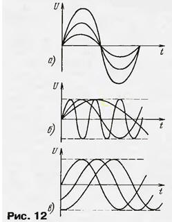
Encyclopedia of radio electronics and electrical engineering / Beginner radio amateur In addition to resistors with some resistance, inductors and capacitors can be included in electrical circuits. For direct current, their behavior is simple and obvious - the coil has some resistance, usually small, equal to the resistance of the wire with which it is wound, and the current capacitor does not conduct, and its resistance can be considered infinitely large (an exception is oxide capacitors, which have a small leakage current). These elements behave completely differently on alternating current. In particular, an induction EMF appears at the coil terminals, and the current begins to flow through the capacitor, periodically recharging the plates. Let's talk about this in more detail. Alternating current is so named because it changes continuously with time. You can come up with many different types of alternating current, but usually we are dealing with a periodic process that repeats itself after a certain time interval, called the period T. The reciprocal of it is called the frequency of the process: f \u1d XNUMX / T. This is the number of oscillations or cycles per second. The shape of the vibrations is also important. The best way to observe it is with an oscilloscope. Oscillations can be a periodic sequence of pulses, rectangular, triangular, and, in general, whatever you like. But it turns out that any, the most complex periodic oscillation can be represented as a sum of the simplest, sinusoidal oscillations with frequencies f, 2f, 3f, etc. The first oscillation with a frequency f is called the fundamental harmonic, the subsequent ones are the second, third, etc. harmonics. Mathematically, this is called Fourier series expansion, and in this way, the passage of complex oscillations through various radio circuits is most often analyzed. For now, we will deal with sinusoidal oscillations, as the basis of any more complex analysis. Sinusoidal (harmonic) voltage is described by the function U = Umsin(ωt - φ0), the graph of which is shown in fig. eleven.
The argument of the function is the current time t, depending on which the voltage U changes. The remaining values serve as oscillation parameters: Um - the amplitude value of the voltage, or simply the amplitude; ω = 2πf - angular frequency; φ0 - initial phase. To better understand the meanings of these parameters, in Fig. 12, a, b, c shows how changes in amplitude, frequency, and initial phase affect oscillations.
When talking about alternating voltage or current, they most often mean their effective (effective) values U, I, equal to 0,7 (more precisely, 1 / √2) on amplitude Um, lm, i.e. U = 0,7Um, I = 0,7lm. Calculations can be made both with amplitude and effective values, the result will be obtained, of course, in the same values. It should be noted again that this is true only for a purely sinusoidal signal. Signals of a different form have completely different relationships between amplitude, average and effective values. For a rectangular signal, for example, the amplitude values of voltage and current are equal to the effective ones, and for a signal in the form of short pulses, the amplitude can be ten times greater than the effective value. The average value of a purely alternating current (without a constant component) for a period is equal to zero. The ratio between the amplitude and effective value of a non-sinusoidal signal changes when it passes through circuits with reactive elements, which must always be kept in mind. Pay attention to what values \u0b\u220bare shown by the measuring instruments you use. A simple example of measuring mains voltage: a magnetoelectric system voltmeter responding to an average value will show 300, an electromagnetic system voltmeter - an effective value of XNUMX V, a voltmeter with a peak detector - more than XNUMX V. But let's get back to the calculations for alternating current. If there are only active resistances in the circuit, the calculation is made in the same way as in DC circuits using Ohm's law and Kirchhoff's rules. Another thing is if inductors and capacitors are installed in the circuit. Ordinary algebra is no longer suitable here, and complex numbers must be used. The total resistance of the inductor is the sum of the active resistance of the wire and the inductive resistance of the winding. The latter has characteristic features: firstly, it grows in proportion to the frequency of the alternating current (at direct current it is equal to zero), and secondly, the voltage that is released on it leads the current by 90 ° in phase. The ratio of the inductive resistance of the coil to the active resistance is called the quality factor and usually ranges from several units for low-frequency coils to several hundreds for high-frequency ones. Capacitors typically have a very high quality factor, and their capacitance is inversely proportional to frequency. The voltage across the capacitor is 90° out of phase with the current. Inductive and capacitive resistances are called reactive. Unlike active ones, power is not dissipated on them - it can only accumulate in the coil and capacitor and be given back to the circuit. For this reason, reactances are not real, but imaginary quantities, and in calculations, the sign j = √ is placed before their designation-1. Further, all algebraic operations are performed in the usual way, taking into account the rules: 1/j = -j, j2 = -1. The total resistance of the circuit Z = r + jX contains a real part - active resistance r and an imaginary part - reactance X, and XL = jωL, XC - 1/jωC = - j/ωC. Inductive XL and capacitive resistance XC have different signs, which indicates the lead or lag of the voltage on this resistance relative to the current. In some cases it is useful to know the absolute value, or the impedance modulus IZI=√r2+X2. As an example, let's find the total resistance of a circuit containing a resistor, an inductor and a capacitor (Fig. 13): Z=r+jωL+1/jωC = r+j(ωL-1/jωC) = r+jX.
We see that the active resistance r does not depend on frequency, while the reactive X depends, and quite significantly. On fig. 14 shows graphs showing how the inductive, capacitive and total reactance of the circuit X changes with frequency. The latter vanishes at a certain frequency ω0 - the resonant frequency.
At the resonant frequency, the inductive reactance is equal to the capacitive one, and their signs are different, so they are compensated. Easy to find: ω0L = 1/ω0С; ω02 = 1/LC. From here, the well-known Thomson formula for the resonant frequency of an oscillatory circuit consisting of a coil and a capacitor is obtained: f0 = 1/(2π√LC). Since we are talking about the circuit, it is useful to mention another important parameter - the quality factor of the circuit. It is equal to the ratio of the modulus p of the reactance of the coil or capacitor at the resonant frequency (where they are equal) to the active resistance r: Q = p / r. If the capacitor has negligible losses, which is usually the case, then the quality factor of the circuit is equal to the quality factor of the coil. The reactance at the resonant frequency can be found without calculating the resonant frequency itself: p = √L / C. The quality factor is maximum (constructive) and can reach several hundred if the resistance r is only the resistance of the coil wire and no additional resistances are included in the circuit. The total resistance of the circuit shown in fig. 13 can be depicted as a point in the coordinate system, where active resistances are plotted along the horizontal axis, and reactive resistances along the vertical axis (Fig. 15).
This is how numbers are usually depicted on the complex plane. At low frequency, capacitive (negative reactance) predominates in the circuit and the point is located well below the horizontal axis (case ω→0). At the resonant frequency, Z = r, and X = 0. At frequencies above the resonant frequency, the point will be located above the horizontal axis (case ω-∞). The locus of all points for different frequencies forms a vertical straight line, and at any frequency it is very easy to graphically find the impedance modulus, as shown for some frequency ω>ω0. Now let the circuit outputs (see Fig. 13) be connected to an alternating voltage source U (standard signal generator with negligible internal resistance), the frequency of which can be changed (Fig. 16).
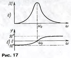
The current in the circuit is still found using Ohm's law: I = U/Z. Of course, the current will be alternating, with the same frequency as the source, and if U is the effective value of the voltage, then I will be the effective value of the current. But Z is a complex quantity! The current value will also turn out to be complex, which means the phase shift of the current relative to the applied voltage. Let's do it simpler: divide the voltage by the impedance modulus and get the current modulus: |l| =U/|Z|. Need to know the phase of the current? We already have it - this is the angle <p on the graph in Fig. 15. Indeed, for low frequencies, the current through the capacitance leads the voltage (φ is negative), at the resonant frequency φ = 0, at high frequencies the current through the inductive resistance lags behind the voltage (φ is positive). Now it is easy for us to build resonant curves - the values of the amplitude (Fig. 17, a) and the phase of the current (Fig. 17, b) in a series resonant circuit depending on the frequency.
Question for self-test. Plot (at least approximately) the voltage across the coil and across the capacitor as a function of frequency in this experiment (for the circuit shown in Fig. 16). Try also to answer the question, how many times is this voltage greater (or less) than the generator voltage with a quality factor of the circuit Q - 100? The answer is needed with an accuracy of no more than a few percent. Response. The circuit consists of a series-connected generator, active resistance, inductance and capacitance. In order to find out the voltage on the coil and on the capacitor, it is necessary to multiply the current in the circuit by the resistance of these elements. At the resonant frequency, the reactances of the coil and the capacitor are equal but opposite in sign, so they cancel out. The current in the circuit is U/r. The voltages on the coil UL and the capacitor Uc are equal to each other, out of phase and make Up/r = UQ. Thus, at the resonant frequency, they are Q = 100 times greater than the generator voltage. As the frequency decreases, the current in the circuit decreases, the reactance of the coil also decreases, so the voltage across the coil UL tends to zero. The capacitive resistance increases, so the voltage across the capacitor Uc does not decrease so quickly and tends not to zero, but to the generator voltage U. This is easy to see from the circuit in Fig. 16 - at the lowest frequencies, the capacitance is much greater than the inductive and active, so almost all the voltage of the generator is applied to the capacitor. With an increase in frequency (above the resonant one), the current in the circuit and the capacitance decrease and Uc tends to zero. The voltage on the UL coil, due to the increase in its reactance, tends not to zero, but to the generator voltage. The graphs of the frequency dependence of the voltages UL and UC are similar to the current graph (Fig. 17), but the side branches of the graphs are raised, in the first case - on the right (in the high frequency region), in the second case - on the left (in the low frequency region), as shown in rice. 61.
Author: V.Polyakov, Moscow
Machine for thinning flowers in gardens
02.05.2024 Advanced Infrared Microscope
02.05.2024 Air trap for insects
01.05.2024
▪ Artificial intelligence plays football ▪ Scientists have implanted a chip in the brain ▪ Nanomaterial of molecules twisted simultaneously in opposite directions ▪ Dawn probe will explore the dwarf planet Ceres
▪ section of the Electrician website. Article selection ▪ Article He who has ears, let him hear. Popular expression ▪ article What do beavers eat? Detailed answer ▪ article Functional composition of TVs. Directory ▪ article Electronic ignition for a car. Encyclopedia of radio electronics and electrical engineering
Home page | Library | Articles | Website map | Site Reviews
www.diagram.com.ua |


 Leave your comment on this article: