|
|


 Arabic
 Bengali
 Chinese
 English
 French
 German
 Hebrew
 Hindi
Hindi Italian
 Japanese
 Korean
 Malay
Malay Polish
 Portuguese
 Spanish
 Turkish
 Ukrainian
 Vietnamese
|
ENCYCLOPEDIA OF RADIO ELECTRONICS AND ELECTRICAL ENGINEERING Welding transformer with electronic current regulation. Encyclopedia of radio electronics and electrical engineering
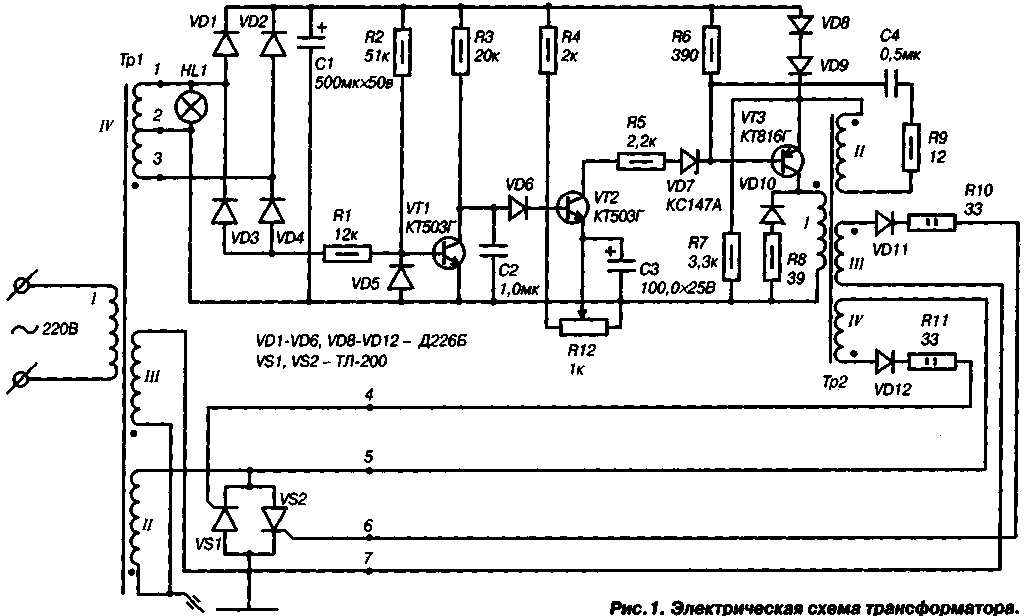
Encyclopedia of radio electronics and electrical engineering / welding equipment This transformer is designed for electric arc welding of structural steel products with electrodes with a diameter of 2-5 mm. It is powered by a single-phase alternating current network with a voltage of 220 V. The electronic current regulator allows you to smoothly change the welding current from 20 to 200 A, which makes it possible to weld parts of various thicknesses. The circuit diagram of the transformer is shown in fig. 1. As follows from the diagram, this device is a type of thyristor-controlled transformer that has become widespread recently. For the manufacture of a transformer and a current regulator, available materials and parts are used.
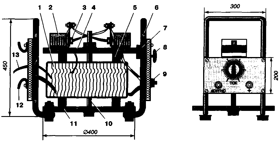
The transformer consists of the actual power transformer Tr1, regulating thyristors VS1 and VS2, included in the power winding circuit II, and an electronic control unit that generates control pulses. Additional winding III stabilizes the burning of the arc and improves the process of its formation at the initial moment of welding. Winding IV feeds the electronic current control unit. Transformer Tr1 is made on the basis of the stator core of an AC induction motor with a power of 15, 18,5 or 22 kW. The engine is disassembled, and the stator, together with the windings, is removed from the housing. In case of difficulty in removing the stator from the housing, the latter is broken, of course, with the necessary precautions. The stator windings are cut out with a chisel and the residues are removed without damaging, however, the stator plates themselves. After that, the magnetic circuit is wrapped with several layers of fiberglass or keeper tape. In the latter case, the insulating material is smeared with epoxy glue or a simple oil varnish, for example, brand PF-231. The primary winding I of the transformer is made with PEV-2 (copper) or APSO (aluminum) wire 02,5 mm and contains 220 turns. The wire is wound evenly over the entire cross section of the magnetic circuit. If there is no wire of the required diameter, then the winding can be done with two wires, while their total cross section should be 5 sq. mm. For the convenience of winding, a shuttle is used, on which the required amount of wire is pre-wound. After manufacturing the winding 1, it is insulated with 2-3 layers of fiberglass or keeper tape. Then it is recommended to check it for the presence of short-circuited turns. To do this, the winding is connected to an alternating current network with a voltage of 220 V. The current in the winding circuit should not exceed 0,3-0,5 A. If the current value exceeds the specified value, then there is nothing left but to rewind the winding more carefully. The secondary winding II is made with a wire with a cross section of 35 mm60, it contains 60 turns. A copper or aluminum bus with reliable insulation can serve as a wire. Next to winding II, winding III is placed on the magnetic circuit, which also contains 2 turns of PEV-02,5 wire 40 mm. Winding IV contains 2 turns of wire VEV-0 0,7 XNUMX mm with a tap from the middle. Windings II, III, IV are insulated, as well as winding I. After the final winding, the transformer should be tested again at no load. With the previously indicated current, the voltage on the windings II and III should be 60 V, and on the winding IV - 40 V. The electronic current control unit is based on a circuit of a similar industrial device, namely, the TC-200 transformer. The wiring diagram of the regulator is carried out in a printed or hinged way, but in any case, the regulator must be enclosed in a reliable case. The Tr2 transformer is wound on a Sh16 magnetic circuit with a set thickness of 16 mm. Its winding 1 contains 140 turns of wire PEV-2 00,5 mm, winding II - 70 turns of wire PEV-2 00,1 mm, windings III and IV each contain 90 turns of wire PEV-2 00,5 mm. Resistors R1 -9 - type MLT-0,5; R10, R11 - type MLT-2; RI2 - type SP2-6A. Capacitors C1 and C3 - type K-50-6; C2 and C4 - type K73. A block assembled without errors and from serviceable parts does not need to be adjusted. Attention should be paid to the correct connection of the windings of the transformer Tr2 and to the observance of the polarity indicated in the diagram. The operation of the unit can be checked using an oscilloscope. To do this, outputs 4-5 and 6-7 are loaded with resistors with a resistance of 50 ohms and a power of 0,5 watts. By connecting the oscilloscope first to one output, then to the other, they make sure that by moving the slider of the resistor R12 the duty cycle of the pulses changes. In the absence of an oscilloscope, the operation of the unit can be checked using an AC voltmeter. Thyristors U81 and VS2 are installed on heat sinks with a total surface of 1000 sq. mm each. One of the options for the design of the welding transformer is shown in Fig. 2. Transformer Tr1 is mounted on a round base with a diameter of 400 mm made of textolite 10 mm thick or plywood 15 mm thick.
Under the transformer, two bars of hard wood with a cross section of 30x30 mm and a length of 350 mm should be placed to ensure air circulation and improve its cooling during operation. The transformer is attached to the base with an M12 coupling bolt of the appropriate length. Radiators with thyristors are mounted on the top plate. The base has two handles for carrying the transformer, made of a steel pipe with a diameter of 1/2". On the second plate there are two brackets for winding the mains cable after work is completed.A circuit breaker rated for a current of at least 6 A can also be installed here. The transformer allows the following mode of its operation: work - 1 hour, break - 10 minutes. Welding is carried out with E-5RA UONI-13 / 55-2,5 UD-1 electrodes of the required diameter in compliance with safety regulations when working with electrical appliances. Welding technology can be found in the relevant manuals. Author: M. Terletsky, St. Petersburg; Publication: N. Bolshakov, rf.atnn.ru
Solidification of bulk substances
30.04.2024 Implanted brain stimulator
30.04.2024 The perception of time depends on what one is looking at
29.04.2024
▪ Fujitsu Raku Raku - a smartphone for pensioners ▪ The most powerful solar power plant launched ▪ Single-layer graphene demonstrates giant magnetoresistance
▪ section of the site Intercoms. Article selection ▪ article Tsar-Hunger. Popular expression ▪ article When was metal first used? Detailed answer ▪ article Modern control systems
Home page | Library | Articles | Website map | Site Reviews
www.diagram.com.ua |

 Leave your comment on this article: