|
|


 Arabic
 Bengali
 Chinese
 English
 French
 German
 Hebrew
 Hindi
Hindi Italian
 Japanese
 Korean
 Malay
Malay Polish
 Portuguese
 Spanish
 Turkish
 Ukrainian
 Vietnamese
|
ENCYCLOPEDIA OF RADIO ELECTRONICS AND ELECTRICAL ENGINEERING Car strobe
Encyclopedia of radio electronics and electrical engineering / Automobile. Electronic devices Motorists are well aware of the importance of the correct setting of the initial ignition timing, as well as the correct operation of the centrifugal and vacuum ignition timing controllers. Improper ignition timing as low as 2-3° and faulty regulators can cause increased fuel consumption, engine overheating, loss of power and can even shorten engine life. However, checking and adjusting the ignition system are rather complex operations that are not always accessible even to an experienced motorist. Automotive stroboscope allows you to simplify the maintenance of the ignition system. With its help, even an inexperienced motorist can check and adjust the initial ignition timing within 5-10 minutes, as well as check the serviceability of the centrifugal and vacuum advance controllers. The operation of a stroboscope is based on the so-called stroboscopic effect. Its essence is as follows: if it illuminates an object moving in the dark with a very short bright flash, it will visually appear as if motionless "frozen" in the position in which the flash caught it. the frequency of its rotation, you can visually stop the wheel, which is easy to see by the position of any mark on it. To set the ignition timing, the engine is started at idle and special installation marks are illuminated with a strobe light. One of them - movable - is located on the crankshaft (either on the flywheel or on the generator drive pulley), and the other is on the engine housing. The flashes are synchronized with the moments of sparking in the glow plug of the first cylinder, for which the capacitive strobe sensor is mounted on its high-voltage wire. In the light of the flashes, both marks will be visible, and if they are exactly one against the other, the ignition timing is optimal, but if the movable mark is displaced, the position of the breaker-distributor is corrected until the marks match. The main element of the device is a pulsed inertia-free stroboscopic lamp H1 type SSH-5, the flashes of which occur at the moments of the appearance of a spark in the candle of the first cylinder of the engine. As a result, the alignment marks made on the flywheel or crankshaft pulley, as well as other engine parts that rotate or move synchronously with the crankshaft, appear stationary when illuminated by a strobe lamp. This allows you to observe the shift between the ignition moment and the moment the piston passes through the top dead center in all engine operating modes, i.e., to control the correct setting of the initial ignition moment and check the performance of the centrifugal and vacuum ignition timing controllers. The electrical circuit diagram of an automobile stroboscope is shown in fig. 1. The device consists of a push-pull voltage converter on transistors VI, V2, a rectifier consisting of a rectifier unit V1 and capacitor C5, limiting resistors R6, R2, storage capacitors C3, C1, a stroboscopic lamp H4, a lamp ignition circuit consisting of capacitors C5, C1 and arrester F4 and protective diode VXNUMX.  Fig.1. Electrical circuit diagram of an automotive stroboscope on germanium transistors. The device works as follows After connecting the terminals X5, X6 to the battery, the voltage converter starts to work, which is a symmetrical multivibrator. The initial opening voltage to the bases of the transistors V1, V2 of the converter is supplied from the dividers R2-R1, R4-R3. Transistors V1, V2 begin to open, and one of them is necessarily faster. This closes the other transistor, since a blocking (positive) voltage will be applied to its base from the winding w2 or w1. Then the transistors V2, V1 open in turn, connecting one or the other half of the winding w1 of the transformer T4 to the battery. In the secondary windings w5, w800, an alternating voltage of a rectangular shape with a frequency of about XNUMX Hz is induced, the value of which is proportional to the number of turns of the windings. At the moment of sparking in the first cylinder of the engine, a high-voltage pulse from the distributor socket through a special plug X2 of the spark gap and capacitors C4, C5 enters the ignition electrodes of the stroboscopic lamp H1. The lamp is ignited, and the storage capacitors C2, C3 are discharged through it. In this case, the energy accumulated in the capacitors C2, C3 is converted into light energy of the lamp flash. After the discharge of capacitors C2, C3, the lamp H1 goes out, and the capacitors are charged again through resistors R5, R6 to a voltage of 420-450 V. This completes the preparation of the circuit for the next flash. Resistors R5, R6 prevent the windings w4, w5 of the transformer from shorting at the time of the flash of the lamp. Diode V4 protects the transistors of the converter if the stroboscope is accidentally connected in the wrong polarity. The spark gap F1, connected between the distributor and the spark plugs, provides the necessary voltage of the high-voltage pulse to ignite the lamp, regardless of the distance between the electrodes of the spark plug, the pressure in the combustion chamber and other factors. Thanks to the arrester, the stroboscope is guaranteed to work even if the spark plug electrodes are shorted. In the case of replacing germanium transistors P214A with silicon ones of the KT837D (E) type, the converter circuit, and indeed the entire stroboscope, must be significantly changed. The data of the transformer is changed and additional requirements are put forward for its execution. This is due to the fact that silicon transistors of the KT837 series are more high-frequency and the circuit made on them is prone to excitation. In addition, to open these transistors, you need more voltage than for germanium transistors. So, for example, if in a stroboscope assembled according to the scheme of fig. 1, solder instead of P214A transistors, for example, KT837D transistors, without changing anything, the converter will not work, both transistors will be closed, in order for the converter to start working, the resistances of resistors R2, R4 must be reduced to 200-300 Ohm. This reduces the efficiency of the converter, and most importantly, without any apparent reason, it can begin to generate high-frequency sinusoidal oscillations with a frequency of 50-100 kHz. supply, prevent the occurrence of high-frequency generation. The power dissipated in the transistors increases dramatically, and the transistor fails after a few minutes. On fig. 2 shows an electrical circuit diagram of an automobile stroboscope on silicon transistors KT837d. The power dissipated in the transistors of the converter, in this case, is much less due to the higher speed of the KT837D transistors, and, consequently, the greater steepness of the fronts of the converter pulses; higher and the reliability of the converter. Consider the features of this scheme. Capacitors C1, C7, connected between the bases of the transistor converters and the minus of the power source, prevent the occurrence of high-frequency generation.  Fig.2. Electrical circuit diagram of a silicon transistor automotive strobe The initial unlocking bias to the bases of transistors V6, V7 is supplied from sufficiently high-resistance voltage dividers R3, R2, R1, R9, R1O, R11 with a total resistance of about 1000 ohms, the lower shoulders of which have a resistance of 100 ohms (division ratio 1/10). However, thanks to the diodes V5, V10, the base current of the transistors from the windings w1, w3 flows through low-resistance resistors R1, R11 (10 ohms). Thus, it is possible to fulfill two conflicting requirements: to obtain a high-resistance divider for the initial bias with a low-resistance resistor in the base current circuit. Circuits C2, R5 and C3, R4 reduce to an acceptable level voltage surges that occur when transistors V6, V8 are closed, which are the result of their excessive speed. The values of C2, C3, R4, R5 are selected experimentally for each specific design of the transformer T1. Resistor R8 ensures the discharge of capacitors C4, C5, C6 in the intervals between these emissions, so that the voltage on the capacitors when the engine is stopped does not exceed the norm. Diodes V7, V9 eliminate reverse current surges of the collector of transistors V6, V8 at the moments of their closing. Without these diodes, the amplitude of the reverse current surge reaches 2 A. In addition, these diodes protect the transistors V6, V8 in case of an erroneous polarity of the stroboscope connection. Unfortunately, the service life of flash lamps is short, and it is not easy to get a new one of the right type. With the appearance on the market of domestic LEDs with a luminous intensity of more than 2000 mcd (for comparison, for LEDs of the ALZO7-M series at the same current, the value of this parameter is 10 ... 16 mcd), it is possible to use them in amateur stroboscopic devices. In the design described below, a group of nine red KIPD21P-K LEDs is used. The device is powered from the on-board network of the car. Diode V1 (see diagram in Fig. 3) protects the stroboscope from erroneous reversal of the supply voltage polarity.  Rice. 3. Electrical circuit diagram of an automotive LED strobe. The capacitive sensor of the device is a conventional crocodile clip, which is attached to the high-voltage wire of the first glow plug of the engine. The voltage pulse from the sensor, passing through the circuit C1 R1 R2, is fed to the clock input of the trigger DD1.1, turned on by a single vibrator. Prior to the arrival of the pulse, the one-shot is in its original state, the direct output of the trigger is low, and the inverse is high. Capacitor C3 is charged (plus from the side of the inverse output), it is charged through resistor R3. A high-level pulse starts the one-shot, while the trigger switches and the capacitor begins to recharge through the same resistor R3 from the direct output of the trigger. After about 15 ms, the capacitor will be charged so much that the flip-flop will again be switched to the zero state on input R. Thus, the single vibrator responds to the pulse sequence of the capacitive sensor by generating a synchronous sequence of high-level rectangular pulses with a constant duration of about 15 ms. The duration of the pulses is determined by the ratings of the RЗСЗ circuit. Positive drops of this sequence start the second one-shot, assembled according to the same scheme on the trigger DD1.2. The pulse duration of the second single vibrator is up to 1,5 ms. At this time, transistors VT1 - VT3, which make up the electronic switch, open, and powerful current pulses - 1 ... 9A flow through the group of LEDs НL0,7-НL0,8. This current significantly exceeds the passport value of the maximum allowable pulsed forward current (100 mA) set for LEDs. However, since the duration of the pulses is short, and their duty cycle in the normal mode is at least 15, overheating and failure of the LEDs were not observed. The brightness of the flashes, which is provided by a group of nine LEDs, is quite sufficient to work with a stroboscope even during the day. In order to verify the reliability of the device, a control electrical run of the light emitter was carried out at a current per pulse of 1 A for an hour. All LEDs passed the test and no overheating was detected. Note that usually the time of using the device does not exceed five minutes. It has been experimentally established that the duration of flashes should be within 0,5 ... 0,8 ms. With a shorter duration, the feeling of a lack of brightness of the illumination of the marks increases, and with a longer duration, their "blurring" increases. The required duration can be easily selected visually while working with a stroboscope with a tuning resistor R4, which is included in the time-setting circuit R4C4 of the second single vibrator. The purpose of the first one-shot is to protect the LEDs from failure if the engine speed is accidentally increased while using the strobe. We have created a model of an automobile stroboscope based on the LED principle (see Fig. 4 (a, b)). The housing is the housing from the lantern.  Fig.4(a). Stroboscope electric assy 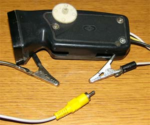 Fig.4(b). Stroboscope electric assy The tests of the assembled device were carried out successfully; it is used in the garage of the Stavropol State Agrarian University. The functions of the stroboscope can be expanded by turning it into a tachometer. Because many older vehicles that are still in service do not have this device on the driver's panel. For this purpose, an adjustable frequency generator (GFR) of 10–15 Hz pulse repetition was assembled, which corresponds to a crankshaft rotation frequency in the range of 600–900 rpm. In this range, the minimum engine speed at idle usually lies, at which the initial ignition timing is adjusted. The handle of the variable resistor included in the frequency-setting circuit of the RC generator was equipped with a scale calibrated using a laboratory digital frequency meter. The MG output signal is input instead of the sensor to the input of the stroboscope. The auto mechanic, having connected the device, directs an intermittent light flux, as in the previous case, the ignition settings to the crankshaft pulley and, if necessary, adjusts it to the value specified by the manufacturer for this vehicle. After adjusting the crankshaft speed, it proceeds to adjust the ignition timing according to the above method, see 1-2. Because the accuracy of determining the crankshaft speed is low, this allowed us to take such a simple solution without resorting to the development of a digital version of the tachometer. Literature
Author: KRUG; Publication: cxem.net
See other articles Section Automobile. Electronic devices
Air trap for insects
01.05.2024 The threat of space debris to the Earth's magnetic field
01.05.2024 Solidification of bulk substances
30.04.2024
▪ section of the site Application of microcircuits ▪ magazines I am an electrician (annual archives) ▪ book Elements of hydroautomatics. Lemberg M.D., 1962 ▪ article Optimistic tragedy. Popular expression ▪ article Pomeranian. Legends, cultivation, methods of application ▪ article Guessing the sum of numbers on a cube. Focus Secret ▪ reference Entering the foreign TV service mode. Book #24
Home page | Library | Articles | Website map | Site Reviews
www.diagram.com.ua |

 Leave your comment on this article: