|
|


 Arabic
 Bengali
 Chinese
 English
 French
 German
 Hebrew
 Hindi
Hindi Italian
 Japanese
 Korean
 Malay
Malay Polish
 Portuguese
 Spanish
 Turkish
 Ukrainian
 Vietnamese
|
ENCYCLOPEDIA OF RADIO ELECTRONICS AND ELECTRICAL ENGINEERING Car ignition timing corrector
Encyclopedia of radio electronics and electrical engineering / Automobile. Electronic devices The economic, power and operational parameters of a car engine largely depend on the correct setting of the ignition timing. The factory setting of the ignition timing is not suitable for all cases, and therefore it has to be corrected, finding a more accurate value in the zone between the appearance of detonation and a noticeable decrease in engine power.
It is known that when deviating from the optimal ignition timing by 10 degrees, fuel consumption can increase by 10% [1]. Often it is required to significantly change the initial ignition timing depending on the octane number of gasoline, the composition of the combustible mixture and actual road conditions. The disadvantage of centrifugal and vacuum regulators used on cars is the impossibility of adjusting the ignition timing from the driver's seat while driving. The device described below allows this adjustment.
From devices similar in purpose [2, 3, 4], the electronic corrector differs in the simplicity of the circuit and a wide range of remote setting of the initial ignition timing. The corrector works together with centrifugal and vacuum regulators. It is protected from the influence of the bounce of the breaker contacts and from interference from the vehicle's on-board network. In addition to correcting the ignition timing, the device allows you to measure the speed of the engine crankshaft. The described one differs from the digital corrector [5] in that it provides smooth adjustment of the correction angle, contains fewer parts and is somewhat easier to manufacture. Main Specifications Supply voltage. V 6...17 Current consumption when the motor is not running. A, with closed breaker contacts 0,18 with open breaker contacts 0,04 Starting pulse frequency. Hz ... 3,3...200 Adjustable starting angle of the valve on the distributor, deg .... '20 Limits of remote correction of the valve's angle. deg ........ 13...17 Delay pulse duration, ms: maximum .... 100 minimum .... 0,1 Switching output pulse duration, ms ........ 2.3 Maximum the value of the output switching current. BUT . . . 0.22The operation of the engine at the setting angles specified by the corrector is possible if the impulse from the interrupter is delayed for a while T3=(Fr-Fk)/6n=(Fr-Fk)/180*Fn
where Фр, Фк - the initial ignition timing set by the distributor and the corrector, respectively; n - frequency of rotation of the crankshaft; Fn=n/30 sparking frequency.
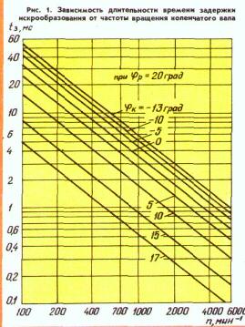
Fig. 1
Figure 1 shows on a logarithmic scale the dependences of the duration of the spark delay time on the crankshaft speed, calculated for different values of the initial ignition timing set by the corrector. This graph is convenient to use when setting up and calibrating the device.
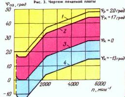
Fig. 2
On fig. 2 shows the characteristics and limits for changing the current value of the ignition timing depending on the speed of the engine crankshaft. Curve 1 is shown for comparison and illustrates this dependence for a centrifugal regulator with an initial ignition timing of 20 degrees. Curves 2, 3, 4 - resulting. They were obtained during the joint operation of a centrifugal regulator and an electronic corrector at installation angles of 17, 0 and -13 degrees.
The corrector (Fig. 3) consists of a start-up unit on a transistor VT1, two waiting multivibrators on transistors VT2, VT3 and VT4, VT5 and an output key on a transistor VT6. The first multivibrator generates a spark delay pulse, and the second controls the transistor switch.
 Rice. 3 (click to enlarge) Assume that in the initial state the breaker contacts are closed, then the transistor VT1 of the start node is closed. The forming capacitor C5 in the first multivibrator is charged with current through the emitter junction of the transistor VT2, resistors R11, R12 and the transistor VT3 (the charging time of the capacitor C5 can be controlled by the resistor R12). Forming capacitor C8 of the second multivibrator will also be charged. Since the transistors VT4 and VT5 are open, VT6 will also be open and will close the "Interrupter" output of the ignition unit through resistor R23 to the case.
When the contacts of the breaker open, the transistor VT1 opens, and VT2 and VT3 close. Forming capacitor C5 begins to recharge through the circuit R7R8R14VD5R13. The parameters of this circuit are chosen so that the capacitor is recharged much faster than its charging. The recharge rate is controlled by resistor R8.
When the voltage on the capacitor C5 reaches the level at which the transistor VT2 opens, the multivibrator returns to its original state. The more often the breaker contacts open, the lower the voltage is charged to the capacitor C5 and the shorter the duration of the pulse generated by the first multivibrator. This achieved an inversely proportional relationship between the spark delay time and the engine speed.
The decay of the pulse generated by the first multivibrator through the capacitor C7 starts the second multivibrator. It generates a pulse with a duration of about 2,3 ms. This pulse closes the VT6 transistor switch and disconnects the "Interrupter" clamp from the body and thereby simulates the opening of the breaker contacts, but with a delay of time t, determined by the duration of the pulse generated by the first multivibrator.
The HL1 LED informs about the passage of the pulse from the sensor-interrupter through the electronic corrector to the ignition unit. Resistor R23 protects the VT6 transistor if its collector is accidentally connected to the positive wire of the car's on-board network.
The protection of the device from the bounce of the breaker contacts is provided by the capacitor C1, which creates a time delay (about 1 ms) for closing the transistor VT1 after the breaker contacts are closed. Diodes VD1 and VD2 prevent the discharge of the capacitor C) through the breaker and compensate for the voltage drop that occurs on the conductor connecting the engine to the car body when the starter is turned on, which increases the reliability of the electronic corrector during engine start. The device protects the VD8C9 circuit, VD6, VD7 zener diodes, R2, R6, R15 resistors and capacitors C2, SXNUMX, Sat from interference arising from the on-board network.
The crankshaft speed is measured by the VD9VD10R25R26PA1 circuit. The scale of this tachometer is linear, since the voltage pulses on the collector of the transistor VT5 have a constant duration and amplitude provided by the zener diode V07. Diodes VD9, VD10 eliminate the effect of residual voltage on transistors VT5, VT6 on the tachometer readings. The rotational speed is counted on the scale of the PA1 milliammeter with a current of full deflection of the arrow 1 ... 3 mA.
The corrector used capacitors K73-17 - C1, C8, C9; K53-14-C2, C5; K10-7 - SZ, C6; KLS - C4. C7. Resistor R8 - SDR-12a, R12 - SDR-6, R23 - is composed of two MLT-0,125 resistors with a resistance of 10 ohms. Diodes KD102B, KD209A can be replaced with any of the series KD209 or KD105; KD521A - on KD522. KD503, KD102, KD103, D223 - with any letter index. Zener diodes KS168A, D818E can be replaced with others with the appropriate stabilization voltage. Transistors KT315G can be replaced with KT315B, KT315V, KT342A, KT342B; KT361 G - on KT361B, KT361V, KT203B, KT203G; KT815V - on KT608A, KT608B.
The details of the device are mounted on a printed circuit board made of foil fiberglass with a thickness of 1 mm. A drawing of a printed circuit board and the location of parts on it are shown in fig. four.
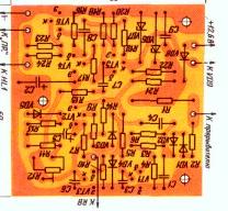 Fig. 4 To set up the device, a power supply with a voltage of 12 ... 14 V is required, designed for a load current of 250 ... 300 mA. A resistor with a resistance of 23 ... 150 Ohms with a power dissipation of 300-1 W is connected between the conductor from the resistor R2 and the positive terminal of the power source for the time of tuning. A breaker simulator is connected to the input of the device - an electromagnetic relay. Use an open pair of contacts; one of them is connected to the common point of resistors R1, R2, and the second - to a common wire. The relay winding is connected to a generator that switches the relay at a frequency of 50 Hz. In the absence of a generator, the relays can be powered from a step-down transformer connected to the network.
After turning on the device, check the voltage at the zener diode VD6 - it should be 6,8 V. If the corrector is assembled correctly, then the HL1 LED should light up when the breaker simulator is running.
In parallel with the transistor VT3, a DC voltmeter with a scale of 2 ... 5 Vs is connected with a current of full deflection of the arrow of not more than 100 μA. The resistor slider R8 is brought to the extreme right position. When the chopper simulator is running, a voltage of 12 V is set on the voltmeter scale with a trimming resistor R1,45. At this voltage, the duration of the delay pulse should be 3,7 ms, and the initial angle 03 is equal to -13 degrees. In the middle position of the slider of the resistor R8, the voltmeter should show a voltage of 1 V, which corresponds to a zero initial angle of the OZ and in the extreme left 0,39 V - 17 degrees (see table).
The most simple (but not quite accurate) corrector can be set up as follows. The slider of the resistor R12 is set to the middle position, and the slider of the resistor R8 is turned by a third of the full angle of rotation from the position of the minimum resistance. Turning the housing of the ignition distributor by 10 degrees in the direction of earlier ignition (against the movement of the shaft), the engine is started and the resistor R12 is used to achieve stable idling. To calibrate the scale of the initial angle regulator, an automobile stroboscope is required.
The tachometer is calibrated by adjusting the resistor R26 (at a triggering pulse frequency of 50 Hz, the microammeter needle should show 1500 min '). If the tachometer is not needed, its elements can not be mounted.
To connect the corrector, a five-pin socket (ONTs-VG-4-5 / 16-r) is installed in a place convenient for the driver, to the contacts of which the conductors from the on-board network, breaker, ignition unit, housing and tachometer (if provided) are connected. The corrector, mounted in a casing, is installed in the passenger compartment, for example, near the ignition switch.
The corrector can be used in conjunction with the electronic ignition unit described in [6]. It can work with other trinistor ignition systems with both pulsed and continuous energy storage on the capacitor. At the same time, as a rule, no modifications are required in the ignition blocks associated with the installation of the corrector. Literature 1. Fuel economy. Ed. E.. P. Seregina. - M.: Voennmat 2. Sinelnikov A. Device EK-1. - Behind the wheel. 1987, no. 1, p. thirty 3. E. Kondratiev. Ignition timing regulator. - Radio, 1981, No. 11. p. 13-15 4. Moiseevich A. Electronics against detonation. Behind the wheel, 198B No. 8. p. 26 5. Biryukov A. Digital octane corrector. - Radio. 1987, no. 10, p. 34-37 6. Bespalov V. Block of electronic ignition. - Radio. 1987, No. 1, p. 25-27. Publication: cxem.net
See other articles Section Automobile. Electronic devices
Air trap for insects
01.05.2024 The threat of space debris to the Earth's magnetic field
01.05.2024 Solidification of bulk substances
30.04.2024
▪ electronics magazines (annual archives) ▪ Bubbles book. Geguzin Ya.E., 1985 ▪ article What is surrealism? Detailed answer ▪ Freesia article. Legends, cultivation, methods of application ▪ reference Entering the foreign TV service mode. Book #9
Home page | Library | Articles | Website map | Site Reviews
www.diagram.com.ua |

 Leave your comment on this article: