|
|


 Arabic
 Bengali
 Chinese
 English
 French
 German
 Hebrew
 Hindi
Hindi Italian
 Japanese
 Korean
 Malay
Malay Polish
 Portuguese
 Spanish
 Turkish
 Ukrainian
 Vietnamese
|
ENCYCLOPEDIA OF RADIO ELECTRONICS AND ELECTRICAL ENGINEERING CAN bus in modern cars. Encyclopedia of radio electronics and electrical engineering
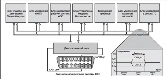
Encyclopedia of radio electronics and electrical engineering / Automobile. Electronic devices The on-board electronics of a modern car includes a large number of executive and control devices. These include all kinds of sensors, controllers, etc. A reliable communication network was required to exchange information between them. In the mid-80s of the last century, BOSCH proposed a new concept for the CAN (Controller Area Network) network interface. The CAN bus provides connection of any devices that can simultaneously receive and transmit digital information (duplex system). The bus itself is a twisted pair. This implementation of the bus made it possible to reduce the influence of external electromagnetic fields arising from the operation of the engine and other vehicle systems. Such a bus provides a sufficiently high data transfer rate. As a rule, the CAN bus wires are orange, sometimes they are distinguished by different colored stripes (CAN-High - black, CAN-Low - orange-brown). Thanks to the use of this system, a certain number of conductors were released from the electrical circuit of the car, which provided communication, for example, according to the KWP 2000 protocol, between the engine management system controller and standard alarms, diagnostic equipment, etc. The data transfer rate on the CAN bus can reach up to 1 Mbps, while the information transfer rate between control units (engine - transmission, ABS - security system) is 500 kbps (fast channel), and the information transfer rate of the Comfort system " (control unit for airbags, control units in the car doors, etc.) of the information and command system is 100 kbps (slow channel). On fig. 1 shows the topology and waveform of the CAN bus of a passenger car. When transmitting information from any of the control units, the signals are amplified by the transceiver (transceiver) to the required level.
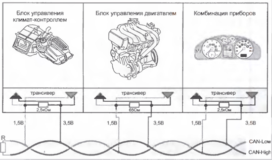
Each unit connected to the CAN bus has a certain input impedance, resulting in a total load on the CAN bus. The total load resistance depends on the number of electronic control units and actuators connected to the bus. So, for example, the resistance of control units connected to the CAN bus of the power unit is on average 68 ohms, and the Comfort system and the information and command system are from 2,0 to 3,5 kOhm. It should be noted that when the power is turned off, the load resistances of the modules connected to the CAN bus are switched off.
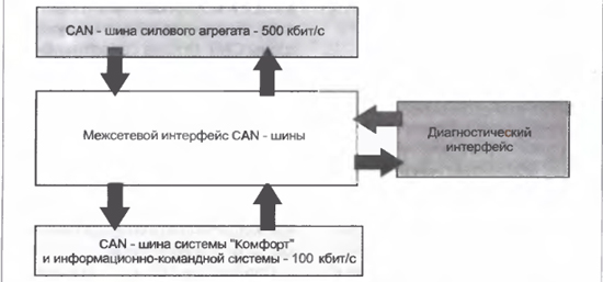
On fig. 2 shows a fragment of CAN buses with load distribution in the CAN-High, CAN-Low lines. Vehicle systems and control units have not only different load resistances, but also data transfer rates, all this can interfere with the processing of signals of different types. To solve this technical problem, a converter is used to communicate between the buses. Such a converter is usually called a gateway, this device in a car is most often built into the design of the control unit, instrument cluster, and can also be made as a separate unit. Also, the interface is used to input and output diagnostic information, the request of which is implemented via the "K" wire connected to the interface or to a special CAN bus diagnostic cable. In this case, a big plus in carrying out diagnostic work is the presence of a single unified diagnostic connector (OBD block). On fig. 3 shows a block diagram of a gateway.
Please note that on some car brands, for example, on the Volkswagen Golf V, the CAN-buses of the "Comfort" system and the info-command system are not connected by a gateway. The table shows the electronic blocks and elements related to the CAN-buses of the power unit, the Comfort system and the information and command system. The elements and blocks shown in the table may differ in their composition depending on the brand of the car. Diagnostics of CAN-bus faults is performed using specialized diagnostic equipment (CAN-bus analyzers), an oscilloscope (including those with a built-in CHN bus analyzer) and a digital multimeter. As a rule, work on checking the operation of the CAN bus begins with measuring the resistance between the bus wires. It must be borne in mind that the CAN buses of the Comfort system and the information and command system, unlike the bus of the power unit, are constantly energized, therefore, to check them, one of the battery terminals should be disconnected. The main malfunctions of the CAN bus are mainly related to the short circuit / open circuit of lines (or load resistors on them), a decrease in the level of signals on the bus, and violations in the logic of its operation. In the latter case, only a CAN bus analyzer can provide a defect search. CAN bus of a modern car
Publication: radioradar.net
Artificial leather for touch emulation
15.04.2024 Petgugu Global cat litter
15.04.2024 The attractiveness of caring men
14.04.2024
▪ Subcutaneous fingerprint scanner ▪ Origins of human speech found ▪ Purification of water and soil from cadmium
▪ site section Measuring equipment. Article selection ▪ article Pull the strap. Popular expression ▪ Mount Cook article. Nature miracle ▪ article Unfolding newspaper. Focus Secret
Home page | Library | Articles | Website map | Site Reviews
www.diagram.com.ua |

 Leave your comment on this article: