|
|


 Arabic
 Bengali
 Chinese
 English
 French
 German
 Hebrew
 Hindi
Hindi Italian
 Japanese
 Korean
 Malay
Malay Polish
 Portuguese
 Spanish
 Turkish
 Ukrainian
 Vietnamese
|
ENCYCLOPEDIA OF RADIO ELECTRONICS AND ELECTRICAL ENGINEERING Automotive stroboscope from a laser pointer. Encyclopedia of radio electronics and electrical engineering
Encyclopedia of radio electronics and electrical engineering / Automobile. Electronic devices Motorists know how important it is to correctly set the ignition timing of fuel in the cylinders of a carburetor engine. For this, strobe lights are used. In the article by P. Bialiatsky "LED car strobe"(Radio, 2000, No. 9) describes a simple device with a flashlight in the form of an assembly of bright LEDs instead of a flash photolamp. The author of this article proposes to assemble a device based on a laser pointer. The stroboscopic device offered to the attention of readers allows not only to set the optimal ignition timing (OZ) at idle engine speed, but also to find a faulty spark plug, check the operation of the ignition coil, control the operation of the centrifugal and vacuum angle regulators 03 at a crankshaft speed of up to 3000 min-1 (high frequency is dangerous for the motor running without load). The device is not designed for use at service stations, but can provide an invaluable service to a car enthusiast who is stuck on the road due to malfunctions in the ignition system. The stroboscope scheme is shown in fig. 1. Pulses from a high-voltage candle wire, passing through the input node, consisting of a differentiating circuit C1, R2 and a limiting resistor R1, start a single vibrator assembled on elements DD1.1, DD1.2. The output pulses of a single vibrator with a duration of about 0,15 ms are fed to the base of the composite transistor VT1VT2, which operates as a current amplifier. The collector circuit of the transistor includes a laser pointer BL1, which serves as the load of the amplifier. Since the output pulses of the single vibrator have a high level, for the duration of their action, the composite transistor opens and the laser of the pointer forms light flashes.
The pointer is designed for a supply voltage of 4,5 V, and in the stroboscope it operates from the on-board network with a voltage of 13,8 V, so the duration of the output pulses of the single vibrator should not exceed 0,15 ms - the value was selected experimentally and cost several "burned out" lasers. With a pulse duration of more than 0,15 ms, the average power dissipated by the laser reaches the maximum allowable and the risk of burning the pointer increases sharply, and with a shorter mark on the crankshaft pulley it becomes visually "hard to see". It must also be remembered that a flash frequency of more than 100 Hz (corresponding to an engine crankshaft speed of 3000 min-1) is dangerous for a pointer operating at high voltage. Structurally, the stroboscope consists of an ignition pulse sensor attached to the spark plug wire of the first engine cylinder, and the pointer itself, inside which all other parts are placed. The sensor is connected to the pointer with a shielded cable 50 cm long. The basis of the ignition pulse sensor is a clothespin, on the side face of which there are parts C1, R1, R2 of the input node. On one of the halves of the clothespin in the place where the working half-hole is located, a coil of tape no more than 3 mm wide is wound from tin or thin-sheet copper in the form of a bandage (Fig. 2). The output of the capacitor C1 is soldered to it. The output of the resistor R1 is soldered to the central wire of the connecting cable, and the resistor R2 is soldered to the screen. The cable is attached to the handle of the clothespin with a wire bandage. From above, the details of the inlet assembly should be covered with silicone sealant and protected from impacts with a textolite bar (not shown in the figure).
To install the stroboscope parts, the pointer must first be disassembled. Having unscrewed the nozzle, a puller ring with an axial thickness of 1 ... 2 mm is installed under it so that it rests against the edge of the cylindrical casing. Then the nozzle is screwed on with force, gradually pressing out the "stuffing" from the casing. If necessary, the operation is repeated with a thicker ring. Attempts to disassemble the pointer without a puller ring usually result in damage to the edge of the casing, made of soft aluminum alloy. Squeezing the "stuffing" out of the casing from the side of the battery compartment, as practice has shown, is also associated with a high risk of damage to the pointer. A push-button switch is soldered from the board of the disassembled pointer (Fig. 3) and with side cutters, carefully, so as not to damage the resistor, shorten it to a dashed line (printed conductors are shown in gray). If the resistor still turned out to be damaged, it does not matter, it is enough to close its conclusions with a jumper, and increase the resistance of the resistor R5 in the circuit (see Fig. 1) to 270 Ohms.
The details of the single vibrator and the output current amplifier are placed on a printed circuit board made of fiberglass laminated on both sides with a thickness of 0,5 mm. The board drawing is shown in fig. 4 (a - print side; b - detail side). Both transistors and capacitor C2 are soldered from the print side directly to the printed pads.
The holes for the microcircuit should be such that it can be mounted as close to the board as possible - this will make it easier to insert the board into the casing of the pointer during assembly. Pin 7 of the microcircuit and one of the pins of the resistor R3 must be soldered on both sides of the board. Since the board is rather "tight", try to think over the sequence of mounting parts in advance so that you do not have to solder the already installed ones later. Mount the chip last. The square-shaped contact pads on both sides of the board must be connected with pieces of copper wire and soldered. A thin insulating gasket should be placed under the transistor VT2. Before connecting the assembled stroboscope board to the prepared pointer board, it is advisable to check its operation with an LED instead of a laser. An LED (for example, AL307B) is temporarily soldered with the anode to the positive power terminal, and with the cathode to the resistor R5. In order to be able to adjust the stroboscope in the laboratory, it is advisable to assemble according to the scheme in Fig. 5 test multivibrator. It generates short high-level pulses with a repetition rate controlled by a variable resistor R2. The pulses are fed to the input of the stroboscope and the resistor R3 is selected so that the duration of the output pulses does not exceed 0,15 ms. After that, you need to make sure that the assembled board freely enters the casing of the pointer. Three flexible leads are soldered to the assembled board - a common, input (to the sensor resistor R1) and positive power (+13,8 V), apply it to the pointer board with connecting foil pads outward, insert into both assembly holes of the boards along a piece of copper wire with a diameter of 0,5 .3 mm and solder. Do not forget to connect the positive output of the laser on the pointer board (see Fig. XNUMX) to the positive power wire on the stroboscope board with a separate conductor. Check again if the structure will fit into the pointer housing. If everything is in order, an insulator made of a thin rigid plastic film rolled into a tube is inserted inside the casing and a laser with a board is inserted into it. The end with the conclusions of the pointer is filled with sealant. Flexible power leads are equipped with alligator clips with polarity markings or a connector for connecting to a portable lamp socket. In all cases, it is advisable to introduce a diode into the break in the positive wire, which protects the stroboscope from accidentally turning on the stroboscope in reverse polarity (this diode is not shown in the diagram in Fig. 1). Any diode with a reverse voltage of at least 50 V and an average rectified current of at least 100 mA will do. You can mount the diode near the crocodile clip. In addition, given that the laser pointer housing is electrically connected to the positive power wire, it must be carefully insulated and not allowed to come into contact with vehicle parts during use. Nevertheless, it will be easier to work with a stroboscope if you include a miniature 0,16 A fuse in series with the protective diode (also not shown in the diagram).
For the operation of the stroboscope, the clothespin sensor is attached to the high-voltage spark plug wire of the first cylinder of the engine. Triggering pulses enter the device through a capacitance between the high-voltage wire and the bandage in the working opening of the sensor. The capacitance should be the minimum required for a stable start. If the capacitance is chosen excessively large, the amplitude of the triggering pulse, under adverse circumstances, may exceed the allowable for the microcircuit and cause its damage. Therefore, at the beginning, the sensor should be installed on the wire through a dry gasket 1 mm thick made of polyethylene or PVC. If the strobe does not start - there is no blinking laser light at the lowest engine speeds - the gasket must be replaced with a thinner one. It is more convenient to work with a stroboscope when its light spot has an elongated shape - this makes it easier to fix both marks in the field of view. Therefore, one of the attached nozzles is put on the pointer, pulling the stain into a line. When working in the daytime, but in the shade, you can do without a nozzle (the brightness of the spot will be greater), directing the beam only at the moving mark. The fixed mark on the case will be clearly visible under these conditions. To protect the laser and handpiece from dirt and dust during storage, choose a suitable plastic case for it. Perhaps it will seem easier for someone to assemble a stroboscope single vibrator on a miniature K564LE5 chip. The board drawing for this option is shown in fig. 6. Here, on the side of the parts (Fig. 6, b), only the capacitor C2 and the transistor VT2 are soldered, the rest of the parts are on the print side. In addition, pin 2 of the microcircuit is connected to the input node. Before working with the strobe light, wipe off the white paint on the marks on the body and crankshaft pulley of the car engine. If the marks are not colored, you should definitely do this - it will be very useful in the future. Move the well-warmed engine to idle speed of 600...800 min-1. Connect the stroboscope power clamps so that its power wires do not come into contact with high-voltage ones. Install the sensor on the high-voltage wire of the first spark plug and point the laser beam at the fixed mark located on the housing. Then find the moving mark on the flywheel pulley with a laser beam - the brightness of the spot in this place increases due to reflection from the white paint. If the mark is not colored, the brightness of the reflected beam, on the contrary, will decrease, but this is more difficult to fix, especially in bright light. You can make sure that the found place is really a mark by slightly changing the engine shaft speed, while the mark moves forward or backward along the pulley rotation. If your vehicle's ignition timing is incorrect, the movable mark may be far away from the fixed mark. At idle, the mark on the flywheel pulley should be opposite the middle fixed mark, i.e., the ignition timing should be equal to 5 degrees. By rotating the body of the ignition switch-distributor, achieve the coincidence of the movable and fixed marks and fix it in this position. Briefly increase the speed and observe the discrepancy between the marks. With an increase in the frequency of rotation of the crankshaft, the ignition should become earlier. At a speed of 3000 min-1, the ignition timing for VAZ vehicles should be within 15 ... 17 degrees. [2]. Do not increase the speed beyond 3000 min-1 - this is dangerous for both the engine and the laser pointer. Never direct the laser beam into your eyes! The stroboscope uses a laser pointer with a power of up to 1 mW. Recently, laser pointers five times brighter have appeared on the market. They have the same dimensions, and their use in an automotive strobe is preferable. Literature
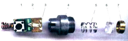
Author: N.Zaets, pos. Veydelevka, Belgorod region; Radio #1 2004 Addition "Car stroboscope from a laser pointer" - under such a heading in "Radio", 2004, No. 1, p. 45, 46 an article by N. Zayets was published. I liked the idea of using a laser pointer as a strobe light. For those who would like to repeat this design, but do not know the device of the pointer, I propose to get acquainted with it in more detail. The figure shows the "stuffing" of the keychain pointer. The light source is a semiconductor emitting crystal 3, soldered to a massive base that serves as a heat sink 2. The heat sink is attached to the board 1, on which the power button, current-limiting resistor and spring contact of the power battery are mounted. The heat sink with the board is tightly inserted into the slot of the sleeve-holder 4, at the other end of which the external and internal threads are cut.
The light from the crystal is strongly scattered and is collected in a thin beam by lens 6. The position of the lens relative to the crystal can be adjusted with a threaded sleeve 7. Spring 5 presses the lens against the sleeve. To use the pointer as a strobe illuminator, it is better to defocus the beam of light by screwing the sleeve in until it stops (but do not press hard!). As a result, the diameter of the light spot at a distance of 1 m will increase to about 6 cm. At a shorter distance, the spot diameter will be smaller. In any case, with a spot wider than the dot, it is easier to "keep" the mark on the engine pulley, and there is less danger to vision if the beam accidentally hits the eyes. Many articles emphasize that the pointer is powered by a 4,5 V source, but the presence of a current-limiting resistor in its design suggests that the voltage can be anything, just select the required current. This is how the laser is turned on in the strobe. To calculate the resistor, you need to measure the pointer laser current and the voltage drop across it. On the laser samples I have, 2,6 V dropped at 35 mA. When choosing a current limiting resistor, do not forget about the built-in 68 ohm resistor. In the process of carrying out experiments on feeding the pointer with an overestimated current, one of them was damaged. But, as it turned out, the crystal remained intact, and its thin output burned out. The operation of the laser was restored with a drop of conductive glue. The tools used for this are a sewing needle and a lens 6. Author: A. Chepurin, Chusovoy, Perm region
Artificial leather for touch emulation
15.04.2024 Petgugu Global cat litter
15.04.2024 The attractiveness of caring men
14.04.2024
▪ Earthquake expected in New York ▪ RAM smartphones reached 4 GB ▪ 20-core Apple M1 Ultra processor ▪ The Internet will not replace a doctor
▪ site section Spectacular tricks and their clues. Article selection ▪ article Dance of St. Vitus (Witt's Dance). Popular expression ▪ article Which animal is the tallest? Detailed answer ▪ article chief accountant. Job description ▪ article Seven-channel electronic key. Encyclopedia of radio electronics and electrical engineering ▪ article Match-Phoenix. Focus Secret
Comments on the article: Zhenya R1 is a current limiting resistor. The current at the input of the field worker limits. Personally checked!
Home page | Library | Articles | Website map | Site Reviews
www.diagram.com.ua |


 Leave your comment on this article: