|
|


 Arabic
 Bengali
 Chinese
 English
 French
 German
 Hebrew
 Hindi
Hindi Italian
 Japanese
 Korean
 Malay
Malay Polish
 Portuguese
 Spanish
 Turkish
 Ukrainian
 Vietnamese
|
ENCYCLOPEDIA OF RADIO ELECTRONICS AND ELECTRICAL ENGINEERING Stereo transmitter of the CCIR system. Encyclopedia of radio electronics and electrical engineering
Encyclopedia of radio electronics and electrical engineering / Microphones, radio microphones The proposed device can be used to provide wireless listening on a VHF receiver of stereo sound accompaniment of various sound reproducing equipment, including as a radio microphone. The article [1] served as the basis for the development. But the device described in it on the BA1404 chip, according to the author, has insufficient output power, much less than the maximum allowed (10 mW), up to which the registration of a high-frequency device is not required [2]. Adding a single-transistor RF amplifier to the BA1404 chip, as described in article [3], also did not allow us to approach this output power level. The problem can be solved using a capacitive three-point generator with a P-loop at the output, successfully used in a radio microphone [4], but it is monophonic, and the author needed a stereophonic device.
In the proposed stereo transmitter, the BA1404 chip controls the generator through a frequency modulator, so the radio frequency components of the chip are not used. The stereo transmitter circuit is shown in fig. 1. The input audio stereo signal is fed to pins 1 (right channel) and 18 (left channel) of the BA1404 (DA1) microcircuit through standard corrective frequency pre-distortion circuits R1R3C1 and R2R4C2, as well as capacitors C3 and C4. The BA1404 chip is a stereo encoder for a CCIR broadcasting system with a sub-carrier frequency of 38 kHz and a pilot tone of 19 kHz. To power the DA1 microcircuit, a 3,3 V parametric voltage regulator is used on the R7 resistor and the VD1 zener diode. The complex stereo signal (CSS) is taken from pin 14 of the DA1 microcircuit, the pilot tone frequency signal from pin 13. The node on resistors R8-R11 and capacitors C11, C13-C15 mixes the signals from these pins in the required proportion. The signal from the output of the node through the resistor R12 is fed to the varicap VD2, included in the circuit L1C16 of the generator on the transistor VT1. Varicap VD2 serves as a frequency modulator. The influence of the dependence of the parameters of the transistor VT1 on the supply voltage on the generation frequency is reduced by choosing a small coefficient of inclusion of the transistor in the circuit, which is determined by the capacitance of the capacitors C18 and C19. To improve the temperature stability of the frequency, these capacitors have a small TKE. The transmitter frequency is 87,9 MHz. The output signal of the generator is taken from the inductor L1 in the collector circuit of the transistor VT1. The L3C23C24 P-loop matches the generator output with the WA1 antenna and suppresses the harmonics of the emitted signal. Antenna WA1 - one telescopic rod about 1 m long when extended from the indoor TV antenna. The stereo transmitter is assembled on a printed circuit board made of double-sided foil fiberglass 1,5 mm thick and 80x50 mm in size. The board drawing is shown in fig. 2.
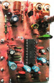
From the side of the parts, the foil is connected to a common wire and left on almost the entire surface of the board, with the exception of the antenna lead, around which it is 2 mm removed. Holes are drilled in the places marked with squares. Pieces of copper wire or leads of the corresponding parts are inserted into them, which are soldered to the foil on both sides of the board. Holes for contacts of parts that do not have a connection to a common wire are countersunk with a metal drill with a diameter of 3.5 mm so as to exclude the short circuit of the conductors inserted into them with a common wire. The appearance of the board is shown in the photo fig. 3.
The stereo transmitter uses MLT, C4-1 resistors, oxide capacitors C3-C5, C9, C11, C21 - imported analogues of K50-35, non-polar constant capacitors - K73-17, K10-17a, and the capacitors C18-C20 must be of the M47 group according to TKE. Trimmer capacitors C16, C23, C24 - KT4-25. Coils L1 and L3 are frameless, wound with PEV wire with a diameter of 0,8 mm. Winding diameter - 5 mm. L1 contains 10 turns, L3 - 7. A small-sized inductor L2 with a measured inductance of 25 μH is taken from an old car radio. A choke with a nominal inductance of 15 ... 30 μH is suitable, in particular, from the DPM-0,1 and DM-0,1 series. To power the transmitter, an industrially manufactured stabilized source IPS-1 with an adjustable output voltage was used. When establishing the L1C16 circuit, it is tuned to a frequency of 87,9 MHz, and the polarity of the inclusion of the VD2 varicap does not play a role. Next, the L3C23C24 P-loop is tuned by alternately rotating the rotors of the tuning capacitors C23 and C24, achieving the greatest possible expansion of the reliable reception zone, receiving the signal with a control receiver. The author used a Nokia cell phone radio with a headset that acted as a receiving antenna. With a good setting of the P-loop, the zone of reliable reception in line of sight can reach 100 m. If the stereo effect disappears before approaching the boundaries of this zone, it is recommended to experimentally select the capacitance of the capacitor C14 or the resistance of the resistor R8 in the direction of decreasing. Literature
Author: A. Ekimov
Air trap for insects
01.05.2024 The threat of space debris to the Earth's magnetic field
01.05.2024 Solidification of bulk substances
30.04.2024
▪ Carbon nanotubes against water pollution by microplastics ▪ Car audio monitors the health of the driver
▪ site section Computer devices. Article selection ▪ article And just what was left in the newspapers: he left for Rostov. Popular expression ▪ article What bird does the Mayan pyramid echo resemble? Detailed answer ▪ Reptile article. Tourist tips ▪ article Horn, ivory. Simple recipes and tips
Home page | Library | Articles | Website map | Site Reviews
www.diagram.com.ua |


 Leave your comment on this article: