|
|


 Arabic
 Bengali
 Chinese
 English
 French
 German
 Hebrew
 Hindi
Hindi Italian
 Japanese
 Korean
 Malay
Malay Polish
 Portuguese
 Spanish
 Turkish
 Ukrainian
 Vietnamese
|
ENCYCLOPEDIA OF RADIO ELECTRONICS AND ELECTRICAL ENGINEERING UMZCH in the system unit of the computer. Encyclopedia of radio electronics and electrical engineering
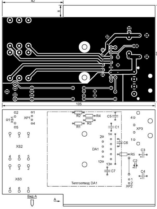
Encyclopedia of radio electronics and electrical engineering / Audio equipment Many of those who like to combine work on the computer with listening to music often face the problem of choosing acoustics. Although there are many models of computer active speakers on sale today, their quality in most cases leaves much to be desired. At the same time, many probably still have small-sized passive loudspeakers with a power of 10 ... 30 W (for example, the Hungarian MiniMax, RTF manufactured by the GDR or domestic 10MAS-1M). They sound much better than modern "soap boxes", but they require a separate UMZCH, which sometimes simply has nowhere to put on a computer desk. Taking into account that for comfortable listening to music during operation, significant power is not required, a version of the UMZCH built into the system unit on the TDA8560Q chip (TDA8560Q 2x40 W / 2 Q stereo BTL car radio power amplifier with diagnostic facility. - URL: nxp.com/ documents/data_sheet/TDA8560Q.pdf). This chip is designed for car audio systems. It consists of two bridge power amplifiers, which, when powered by a unipolar 14,4 V voltage source and a load resistance of 2 ohms, develop an output power of up to 40 W per channel. With an increase in load resistance to 4 ... 8 ohms, the output power decreases to 10 ... 20 W per channel. When the microcircuit is powered by a voltage of 12 V, the output power is approximately 30% less. The schematic diagram of the UMZCH is shown in fig. 1. Its board has the dimensions and shape of a standard computer module (card) inserted into a free PCI slot on the motherboard. At the same time, power is supplied to the UMZCH module directly from the computer's power supply through a separate connector for powering the computer's sound card in two ways: to the XS1 connector with an external shielded cable with a 3,5 mm stereo audio plug or to the XP1 connector from an internal ten-pin connector on the motherboard designed for for connecting additional audio connectors on the front panel of the system unit. See your motherboard manual for the pinout of this connector. The second option allows you to send a signal to the UMZCH without an external connecting cable. When using the XP1 connector, do not solder the XS1 connector to the board, because when a plug is not connected to it, its contacts close the signal circuits to a common wire.
The circuit under consideration differs from that recommended by the manufacturer by the presence of input attenuators at the inputs of each channel. With the values of resistors R1 - R4 indicated in the diagram and at the maximum signal level of a standard sound card, the output power of each channel is about 10 W at a load of 8 ohms. If desired, it can be changed by selecting resistors R1 and R2. A drawing of a UMZCH printed circuit board with dimensions of 105x66 mm and a diagram of the placement of parts on it are shown in fig. 2. There are two jumpers on the board made of a single-core copper wire with a diameter of 0,7 mm. The common wire polygon is divided into "signal" and "power" sections. To avoid self-excitation of the amplifier, do not combine them.
The board is designed to install resistors with a power of 0,125 W, film capacitors with a lead-to-pin distance of 5 mm and oxide capacitors with a diameter of 5 and 10 mm, and a height of no more than 21 mm. Power connector XP3 - angled four-pin plug THP-4MR (Molex). These are usually installed in computer disk drives. Stereo jack XS1 - DTJ-0366D for a standard plug with a diameter of 3,5 mm. Output sockets XS2 and XS3 for plugs with a diameter of 6,3 mm - ST-020 with union plastic nuts. The DA1 chip is placed on the board with a plastic surface, and the heat sink plate is up. To do this, it will be necessary to reformulate its conclusions. This should be done very carefully, since the metal of the leads is rather fragile and does not withstand repeated bending. A heat sink is placed on top of the microcircuit. This "sandwich" is pressed against the board with two screws. The author used a suitable heat sink from an old computer motherboard. Before installing the heat sink, drill two mounting holes in it and cut the M3 thread into them, and apply a small amount of heat-conducting paste to the contact point of the heat sink with the heat sink plate of the microcircuit. Since all film capacitors are placed on the board under the heat sink of the microcircuit, they should be placed on the board by bending the leads. After mounting all the parts, a standard computer blank plate is put on the threaded bushings of the XS2 and XS3 sockets. It is advisable to find a plug from the old system unit - they were made of sheet steel 0,8 ... 1 mm thick and nickel-plated. According to the drawing shown in fig. 3, you need to drill three holes in it for sockets XS1 - XS3. According to the same drawing, you can make a homemade plug. If you use a thinner modern plug, it will need to be handled very carefully so as not to deform when connecting and disconnecting plugs. To facilitate the installation of the UMZCH module into the motherboard connector, I recommend chamfering the edges of the lower protrusion of the board, as shown in Fig. 2 (view A). This will protect the connector pins from damage.
The assembled amplifier does not need to be adjusted. However, it should be remembered that it can consume up to 3 ... 4 A from the computer's power supply (depending on the load resistance and the input signal level). You should not try to "squeeze" the maximum possible power out of the amplifier (2x40 W into a 2 ohm load). With a load with a resistance of 8 ohms, and most small-sized dynamic heads have just such an impedance, and with a power of 8 ... 10 W per channel, the current consumed by the device will not exceed 2 ... 3 A even in peak mode. For modern computer power supplies with a power of 400. ..500W is perfectly safe. In addition, the DA1 chip will not get very hot even with a small heat sink. If you need increased power (up to 25 W per channel), you should install a power supply unit with a power of at least 600 W in your computer - such units are designed for output current through the +12 V circuit up to 10 A. You will also need to install a 50x50 mm fan on the heat sink from video cards. The board has an XP2 connector for connecting a fan. Please note that an amplifier with a fan installed on the computer motherboard will not only occupy its own slot, but also block access to the neighboring one. The amplifier does not have volume and tone controls - their role is played by the software controls of the computer's sound card.
The PCB file in Sprint Layout 6.0 format can be downloaded from ftp://ftp.radio.ru/pub/2017/03/pow-amp.zip. Author: I. Karpunin
Artificial leather for touch emulation
15.04.2024 Petgugu Global cat litter
15.04.2024 The attractiveness of caring men
14.04.2024
▪ Ultra-thin flexible safety glasses ▪ Hybrid crossover Chery Tiggo 7 Plus ▪ Artificial biological tissue ▪ NearLink wireless technology ▪ Restoration of the appearance of a person by his DNA
▪ section of the site Amateur Radio Technologies. Selection of articles ▪ article Poet, do not cherish the love of the people. Popular expression ▪ What was Italy like in the XNUMXth-XNUMXth centuries? Detailed answer ▪ article First aid training for casualties
Home page | Library | Articles | Website map | Site Reviews
www.diagram.com.ua |


 Leave your comment on this article: