|
|


 Arabic
 Bengali
 Chinese
 English
 French
 German
 Hebrew
 Hindi
Hindi Italian
 Japanese
 Korean
 Malay
Malay Polish
 Portuguese
 Spanish
 Turkish
 Ukrainian
 Vietnamese
|
ENCYCLOPEDIA OF RADIO ELECTRONICS AND ELECTRICAL ENGINEERING Use of the 6AC-2 acoustic system with a non-standard amplifying device. Encyclopedia of radio electronics and electrical engineering
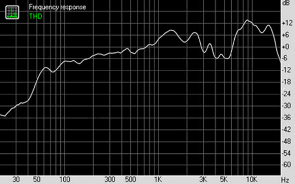
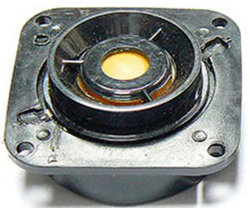
Encyclopedia of radio electronics and electrical engineering / Audio equipment Each acoustic system (AC) 6AC-2 radiol "Melody - 101, 104, 105 - stereo" and their modifications, electrophone Melody - 103, produced by the Riga Radio Plant named after. Popov PO "Radio engineering", consists of two loudspeaker heads (round dynamic direct radiation) installed in a box made of glued plywood 10 mm thick [1]. The loudspeaker heads are mounted in the housing coaxially (axis means axis) relative to each other on a plastic base (no front baffle board). The advantage of this arrangement of loudspeakers is a smooth, dip-free, directivity characteristic, which is impossible to achieve with spaced, even closely spaced, heads. But, on the other hand, all designs of such loudspeakers have one common drawback - due to the interference of sound waves emitted simultaneously by several heads, the total amplitude-frequency characteristic (AFC) of sound pressure, in the zone of their joint action, acquires a number of local peaks and dips on medium and high frequencies. To eliminate this phenomenon, it is necessary either to increase the steepness of the slopes of the frequency response of separation filters (which greatly complicates their design), or to bring the radiation centers of the heads closer together. The absence of a front reflective board entails significant losses due to the diffraction of sound waves (baffl-step effect) - one of the types of distortion that affects the sound quality of any speaker system. This type of distortion manifests itself in the frequency range from 100 to 800 Hz and is a smooth decrease in the acoustic pressure created by the acoustic system below a certain frequency (for 6AC-2, this calculated frequency is 732 Hz). The actually measured loss value is 3-4 dB [2]. To dampen the moving system of the main head Gr 1 (Fig. 1) at frequencies close to the frequency of its mechanical resonance, the entire free volume of the 6AC-2 acoustic system box is filled with cotton wool. In addition, the Gr 1 head is small. All this determined the low sensitivity of the 6AC-2 acoustic system and caused a decrease in its frequency response in the low-frequency region (Fig. 2).
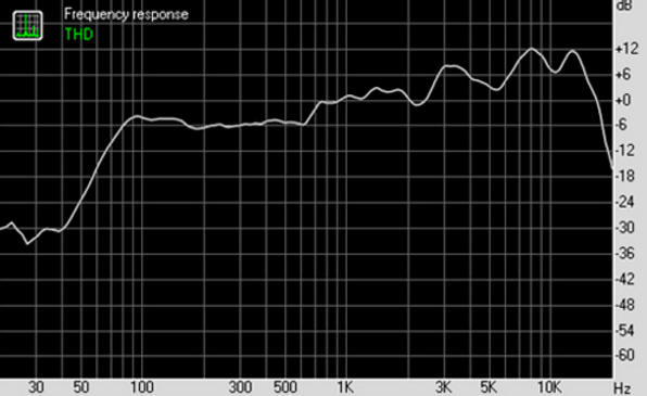
These features of the speakers are compensated by the characteristics of the low-frequency path during the development of Melodies. To equalize the frequency response of the sound pressure of acoustic systems, the LF radiogram path has a frequency response with a significant rise in the low-frequency region (at a frequency of 60 Hz, about 14 dB). The necessary value of sound pressure during the operation of acoustic systems is provided by an increased output power of the low-frequency path (the maximum output power of the Melodiya-101-stereo radiogram is about 15-20 W). It follows from the above that the 6AC-2 and the Melodiya amplifier are designed to work together. To connect the speaker to an abnormal signal source, you need to modify it. Among the shortcomings, it should be noted, also, the vibration of the walls of the case, significant uneven amplitude-frequency characteristics in the mid-range. The latter is due to the fact that the low-frequency head 10GD-34, which also performs the function of the mid-frequency link, has a sharp drop in the frequency response of the sound pressure from 4,5 kHz (Fig. 3, a). The high-frequency head 3GD-2 is switched on through a first-order filter with a cutoff band of 10 kHz. Equalizing the frequency response of the sound pressure at medium frequencies is quite simple - reduce the cutoff frequency of the filter. In a similar AS [3], M. Korzinin installed a filter with a crossover frequency of 4 kHz. However, in this case, the frequency of the main resonance of the RF head, and this is 4,5 kHz, is higher than the cutoff frequency, which is not desirable. The 3GD-2 speaker operating at the frequency of the main resonance cannot provide full-fledged high-quality sound. In addition, the proposed filter is laborious to manufacture (winding two inductors). There is an easier option. To do this, an isolation capacitor of the RF head is installed with a capacity of 8,8 microfarads (film capacitors connected in parallel: two 3,3 microfarads each and one 2,2 microfarads with an operating voltage of 400 V). Since such a refinement will bring the cutoff frequency very close to the frequency of the main resonance of the RF head, the latter is shunted with a 5,4 Ohm resistor with a power of 3 - 5 W. Such a shunt equalizes the frequency characteristics of the sensitivity of the heads, electrical resistances and, most importantly, dampens the resonances of the HF head, including the main one [4]. The latter, at the same time, is connected in antiphase with respect to the low-frequency head (Fig. 4). In the described design, two series-connected 2,7 Ohm resistors with a power of 5 W are used. The total capacitance of the filter capacitors is calculated using an online calculator [5]. The calculation takes into account the total DC resistance of the 16 ohm head and the 5,4 ohm shunt resistor. Thus, the 3GD-2 head will already work with 4,5 kHz, providing full-fledged speaker sound throughout the entire range. It should be noted that one of the design features of the 3GD-2 is the presence of a silk dome diffuser, which provides a relatively flat frequency response of sound pressure from 2 to 18 kHz (Fig. 3, b).
To equalize the sound pressure of the acoustic system in the LF region, following the example of I. Smirnov [6], a phase inverter (FI) is added to the speaker. The author used a plastic pipe with an inner diameter of 50 mm and a length of 100 mm. This decision is correct, since heads with a low (Q < 0,6) quality factor are suitable for the manufacture of AS with FI (for 10GD-34 it is 0,45). The tuning frequency of such a FI is 90 Hz. This value is not acceptable, because the resonant frequency of the 10GD-34 head in open space is 80 Hz, which is the easiest to tune the phase inverter [7]. The optimal (minimum possible) FI tuning frequency for the specified head is 35 Hz. Long-term practice of operating 10GD-34 heads in acoustic design with a phase inverter has determined the best tuning frequency - 55 Hz. Calculate the dimensions of the phase inverter port for the specified frequency using the BassPort computer program. Based on the calculations obtained, a hole with a diameter of 5 mm is cut out in the rear wall of the speaker cabinet (Fig. 35.) and a piece of cardboard tube with an inner diameter of 32 mm and a length of 130 mm is glued into it. On the back wall, a board made of foil fiberglass with dimensions of 50 X 50 mm with filter elements and surface-mounted conductors is also installed. Felt 10 - 15 mm thick or foam rubber is glued onto the remaining free space. The filler (cotton wool) is removed.
In conclusion, the seams of the walls are sealed, the walls themselves are covered from the inside with self-adhesive vibroplast 1,5 mm thick or linoleum, the low-frequency head is provided with soft fastening (elimination of vibrations of the walls of the case). Four rubber feet are mounted on the back wall. After such a simple and simple refinement of 6AC-2, both the objective indicators of measuring the frequency response of sound pressure (Fig. 6) and the subjective examination of listening to music programs note a significant improvement in its sound quality. To test the heads and acoustic system, a measuring microphone, a PC and the RightMark Audio Analyzer 6.2.4 program are used. [8].
Two loudspeakers are placed, following the example of R. Kunafin [4], with speakers facing up. It is allowed to operate 6AC-2 with an amplifying device that delivers power of 15 ... 25 W per channel, which is quite enough to ensure high-quality sound in a room up to 100 m3. For those who consider turning the speaker cabinets inappropriate, the speakers are supplemented with a 1st order link that corrects high frequencies in the baffl-step band (Fig. 7) [8]. This circuit compensates for the rise in the frequency response of the loudspeaker associated with the transition from omnidirectional to half-space radiation. The transition frequency Fd is 700 Hz and the attenuation level N is 6 dB (from the frequency response plot in Fig. 6). In this case, the value of the compensating resistor Rk is assumed to be equal to the load resistance Rn - 4 Ohm, the inductance of the compensating coil Lk is 1,3 mH. More precisely, the resistance of the resistor and the inductance of the coil are selected based on subjective impressions or measurement results.
Literature
Author: Vladimir Marchenko
Artificial leather for touch emulation
15.04.2024 Petgugu Global cat litter
15.04.2024 The attractiveness of caring men
14.04.2024
▪ SpaceX Starship Thermal Insulation Fire Tests ▪ Organic rechargeable household batteries ▪ How to recognize someone else's dream ▪ The most distant object in the solar system discovered ▪ Stress in dogs is associated with the emotional state of the owners
▪ section of the site Palindromes. Article selection ▪ Article Dreaming Dreams. Popular expression ▪ article Accountant of the commodity group. Job description ▪ article A whole coin! Focus secret. Focus Secret
Home page | Library | Articles | Website map | Site Reviews
www.diagram.com.ua |


 Leave your comment on this article: