|
|


 Arabic
 Bengali
 Chinese
 English
 French
 German
 Hebrew
 Hindi
Hindi Italian
 Japanese
 Korean
 Malay
Malay Polish
 Portuguese
 Spanish
 Turkish
 Ukrainian
 Vietnamese
|
ENCYCLOPEDIA OF RADIO ELECTRONICS AND ELECTRICAL ENGINEERING Volume and tone control of a modern stereo complex. Encyclopedia of radio electronics and electrical engineering
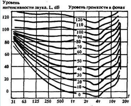
Encyclopedia of radio electronics and electrical engineering / Tone, volume controls The sensitivity of the human ear noticeably depends on the frequency, which is clearly seen from the curves of equal loudness in Fig.1.
To ensure high quality reproduction over the entire volume range, it is necessary to compensate for the corresponding differences in hearing sensitivity. Currently, this problem is solved with the help of volume controls with loudness close to optimal. Many radio amateurs involved in the design of high-quality equipment know how difficult it is sometimes to find a variable resistor with taps for a thinly compensated volume control. Meanwhile, there are several ways to use ordinary resistors for loudness compensation [2], [3]. The controller described in [2] is taken as the basis of the proposed controller (Fig. 4).
In order to obtain the maximum signal-to-noise ratio at low volume, the tone block on a low-noise microcircuit is first turned on and only then the volume control. The rise of the frequency response at frequencies below 300 Hz with a slope of 6 dB / oct. define elements of environmental protection R28,C10. Knee frequency f=1/2-R28C10 The rise in frequency response at frequencies below 100 Hz corresponds to 12 dB / oct., due to the additional action of the circuit R23, C8. The R20C7 circuit helps limit the rise in frequency response at frequencies below 20 Hz. The rise in frequency response at frequencies above f=l/-RC 8 kHz is limited by resistor R25 at 10 dB. If you need a sharp decrease in volume ("intimate" effect), switch S2 is provided. At the same time, the effect of thin-pension remains practically unchanged. With the same switch, it is advisable to change the sensitivity of the power level indicator. Out of compensation for almost all schemes remain frequencies in the region of 3...4 kHz, requiring a cutoff from 4 to 8 dB over the entire range of volume changes in a narrow frequency band, as well as frequencies of 12...16 kHz near the edge of audibility, requiring their steep rise . Taking into account the high level of the other links of the stereo complex (players, tape recorders, tuners, etc.), i.e. having a flat frequency response over the entire sound range, for tone control, as a rule, a two-band tone control is enough. The circuit of the amplifier "Arktur-001" [5] was taken as the basis for the development. In addition to adjusting the tone in the regulator, the signal is amplified three times. This decision made it possible to abandon the normalizing amplifier. In order to eliminate the above disadvantages of a thinly compensated volume control, a third tone control at a frequency of 3,5 kHz was introduced, with which you can get the effect of "presence" by setting the desired rise in the frequency response, as well as more complete compensation by attenuating the signal by 4 - 5 dB. For the same purpose, an inductance was introduced into the RF regulator, which contributes to a steeper rise in the frequency response at a resonance frequency of about 15 kHz. Taking into account the difficulties with ferrite rings (their shortage and the complexity of winding), the inductance of the mid-frequency controller is made on a transistor equivalent - a gyrator. The operation of such a gyrator is described in detail in [6]. The regulators are fed from a bipolar stabilized source with a voltage of + 15V through RC filters 100 Ohm, 100 uF (not shown in the diagram). The equalizer can be used as a non-inertia noise suppressor [7] in the tape recorder path, making a recording with a midrange rise of about 5 - 6 dB and, accordingly, playback with the same blockage. In this case, the noise reduction will be approximately the same 5 - 6 dB. The resonance frequency of the MF is calculated by the formula Fo=1/2-(R6R10C3C4)1/2, where resistors are in kΩ, capacitors are in uF, frequency is in kHz. Substituting the values in the formula, we get: Fo=4 kHz The quality factor of the resonant circuit is equal to two. With C4 equal to 2700 pF, the resonance frequency is 3,5 kHz. All five variable resistors are of the SPZ-33-23P group A type, which are soldered directly into the boards. The volume control is made on a separate board. All electrolytic capacitors are K50-35, the rest are K73-17 or KM-56. Fixed resistors of type C2-23 or MLT with a power of 0,125 W. The inductor is wound on a 2000NM K18x5x5mm ring and contains 100 turns of PEL-1 0,27 wire. Instead of an equivalent inductance (elements R6, RIO, R11, C4, VT1), between points A and B, you can turn on an inductance of 60 MH, 250 turns of PEL-1 0,18 wire on the same ring. In this case, the capacitor C3 with a capacity of 0,01 μF must be replaced with 0,033 μF. In the absence of rings, the inductance L1 can be completely eliminated, while the rise of the RF components of the signal will be in a wider frequency band. References:
Author: A.I.Shikhatov
Alcohol content of warm beer
07.05.2024 Major risk factor for gambling addiction
07.05.2024 Traffic noise delays the growth of chicks
06.05.2024
▪ New Science - Forensic Seismology ▪ Huawei FreeBuds Pro 2+ headphones with thermometer and heart rate monitor ▪ 1600W chargers with 19" rack version ▪ The connection between hunger and curiosity
▪ section of the site Encyclopedia of radio electronics and electrical engineering. Article selection ▪ article I did what I could, let those who can do better. Popular expression ▪ article Which animal survived on three ships that sank in World War II? Detailed answer ▪ article Commandant. Job description ▪ article Smoke detector. Encyclopedia of radio electronics and electrical engineering ▪ article Digital tachometer. Encyclopedia of radio electronics and electrical engineering
Home page | Library | Articles | Website map | Site Reviews
www.diagram.com.ua |


 Leave your comment on this article: